f0dim
2017-11-22 00:34
electronics
This simple addition/hack lets me control the Velleman K8064 DC dimmer kit via wireless OSC or serial. It's based on an ESP8266. The kit is isolated, can dim 220V/110V and is rated for up to 750W loads.
Normally one control it using 0-12V but by replacing a resistor (R16) it's possible to do it with the 0-3.3V PWM signal that the ESP outputs.
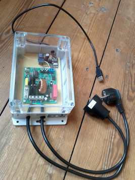
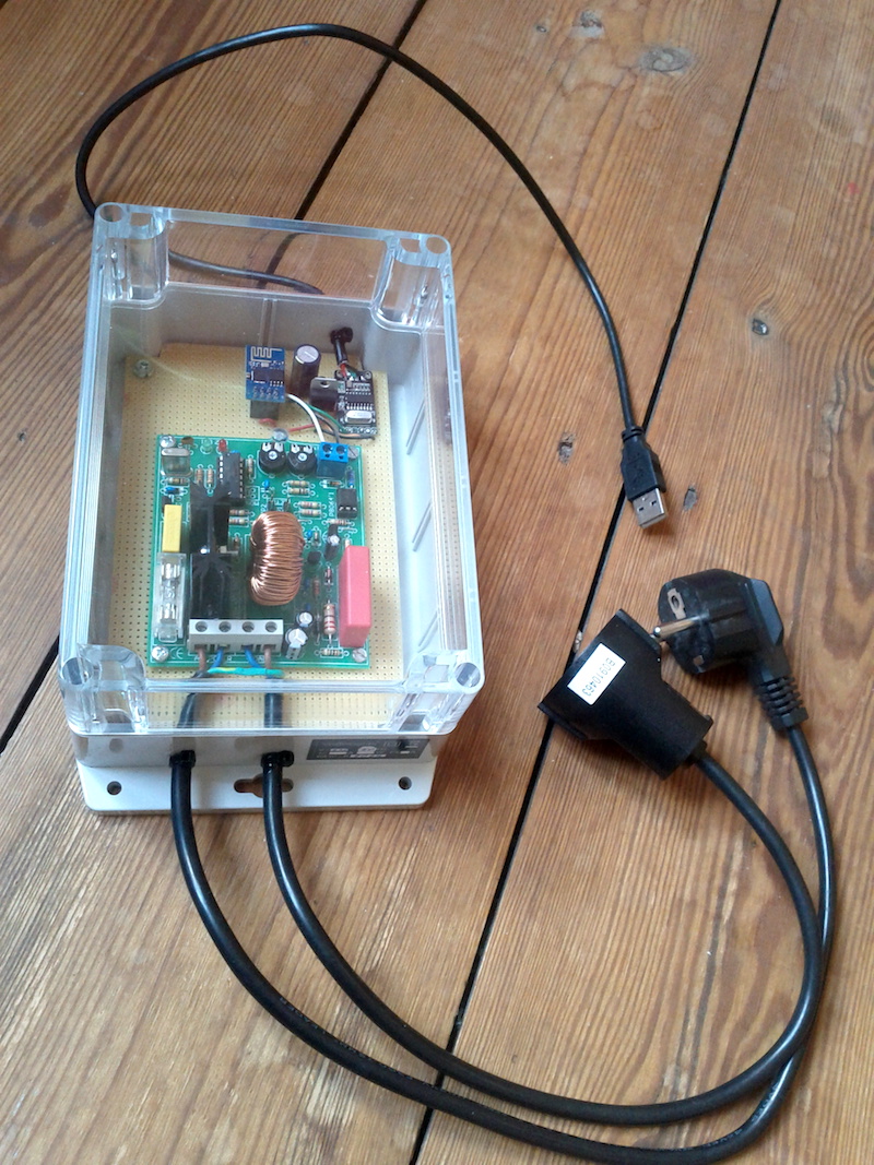
f0dim box
I probably should cut some air ventilation holes, but so far it hasn't gotten hot inside.
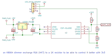
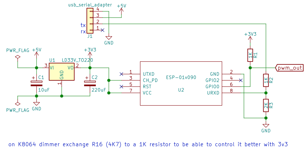
f0dim circuit schematics
Arduino code for the ESP8266...
//f.olofsson2017

// * install OSC from https://github.com/CNMAT/OSC
// * edit where it says EDIT below
// * choose board: "Generic ESP8266 Module" 160 MHz

//OSC protocol: /dim PWM fade
//  PWM should be 0.0-1.0
//  fade should be 0.0-1.0 (1.0=instant)
//serial protocol: 253 254 PWMhi PWMlo fadehi fadelow 255
//  PWM hi and lo should be 0-1023
//  fade hi and lo should be 0-1023 (1023=instant)

#include <ESP8266WiFi.h>
#include <WiFiUdp.h>
#include <OSCMessage.h>

#define PORT 15551  //receiving OSC port
#define PINPWM 0
#define PAYLOAD 4
#define UPDATERATE 16
#define TRIES 100  //how many times try check for wifi connection at startup

const char *ssid = "wifinetwork"; //EDIT your accessPoint network name
const char *password = "wifipassword";  //EDIT your password
const char *espname = "f0dim";
WiFiUDP Udp;
bool wifi;

byte serial_index = 0;
byte serial_data[PAYLOAD];
unsigned long next_time;
float dim = 0.0, dim_target = 0.0, dim_fade = 1.0;

void setup() {
  analogWriteFreq(5000);   //5khz pwm
  Serial.begin(115200, SERIAL_8N1, SERIAL_RX_ONLY);
  pinMode(LED_BUILTIN, OUTPUT);
  pinMode(PINPWM, OUTPUT);
  analogWrite(PINPWM, 0);
  delay(10);
  WiFi.mode(WIFI_STA);
  WiFi.hostname(espname);
  WiFi.begin(ssid, password);
  byte cnt = 0;
  wifi = false;
  while ((WiFi.status() != WL_CONNECTED) && (cnt < TRIES)) {
    delay(100);
    cnt++;
    digitalWrite(LED_BUILTIN, cnt % 2);
  }
  if (WiFi.status() == WL_CONNECTED) {
    Udp.begin(PORT);
    wifi = true;
  }
  digitalWrite(LED_BUILTIN, !wifi); //blue led on if connected to wifi
}

void oscDim(OSCMessage &msg) {
  dim_target = msg.getFloat(0);
  dim_fade = msg.getFloat(1);
}

void loop() {

  //--serial input
  while (Serial.available() > 0) {
    byte val = Serial.read();
    if ((serial_index == 0) && (val == 253)) {
      serial_index = 1;
    } else if ((serial_index == 1) && (val == 254)) {
      serial_index = 2;
    } else if ((serial_index >= 2) && (serial_index < (PAYLOAD + 2))) {
      serial_data[serial_index - 2] = val;
      serial_index++;
    } else if ((serial_index == (PAYLOAD + 2)) && (val == 255)) {
      dim_target = ((serial_data[0] << 8) + serial_data[1]) / 1023.0;
      dim_fade = ((serial_data[2] << 8) + serial_data[3]) / 1023.0;
      serial_index = 0;
    } else {
      serial_index = 0;
    }
  }

  //--OSC input
  if (wifi) {
    int packetSize = Udp.parsePacket();
    if (packetSize) {
      OSCMessage oscMsg;
      while (packetSize--) {
        oscMsg.fill(Udp.read());
      }
      if (!oscMsg.hasError()) {
        oscMsg.dispatch("/dim", oscDim);
      }
    }
  }

  //--fading
  if (millis() >= next_time) {
    next_time = millis() + UPDATERATE;
    if (dim < dim_target) {
      dim = dim + dim_fade;
      if (dim > dim_target) {
        dim = dim_target;
      }
    } else if (dim > dim_target) {
      dim = dim - dim_fade;
      if (dim < dim_target) {
        dim = dim_target;
      }
    }
    analogWrite(PINPWM, int(dim * 1023));
  }
}
SuperCollider example code...
//f0dim can be controlled either via OSC or serial
n= NetAddr("192.168.1.105", 15551);
n.sendMsg(\dim, 1.0, 1.0);  //set 100% instantly
n.sendMsg(\dim, 0.5, 1.0);  //set 50% instantly
n.sendMsg(\dim, 0.0, 1.0);  //set 0% instantly
n.sendMsg(\dim, 1.0, 0.001);  //slow fade in
n.sendMsg(\dim, 0.0, 0.0005);  //slower fade out

SerialPort.listDevices;
(
~port= SerialPort("/dev/tty.usbserial123", 115200, crtscts: true);  //EDIT serialport
CmdPeriod.doOnce({~port.close});
f= {|pwm= 1023, fade= 1023|
  Int8Array[253, 254, pwm>>8, pwm%256, fade>>8, fade%256, 255];
};
)

~port.putAll(f.value(1023, 1023));  //set 100% instantly
~port.putAll(f.value(512, 1023));  //set 50% instantly
~port.putAll(f.value(0, 1023));  //set 0% instantly
~port.putAll(f.value(1023, 3));  //slow fade in
~port.putAll(f.value(0, 2));  //slower fade out

~port.close;