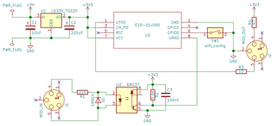
Wireless MIDI <-> OSC bridge using an ESP8266-01. This circuit is extremely cheap to build. Schematics, Arduino code and examples for SuperCollider below.
I'm using the great Arduino MIDI Library that allows for both sending and receiving (see API) a multitude of MIDI messages including SysEx, system realtime and time code messages. My Arduino code just converts all these to/from OSC and send or broadcast them over WiFi network.
Note: sending MIDI over WiFi UDP is generally a bad idea. There will be delays, glitches and even lost messages (hanging notes). This is especially problematic for MIDI time code (sync) messages. That said, in many situations this is ok and in my tests with a simple note on/off messages + bend and control, things seem to work just fine.
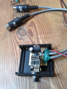
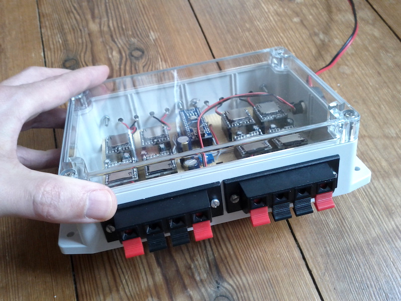
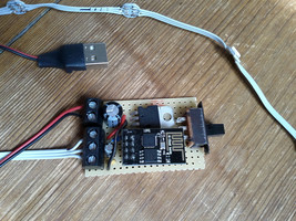
inside the f0mid box
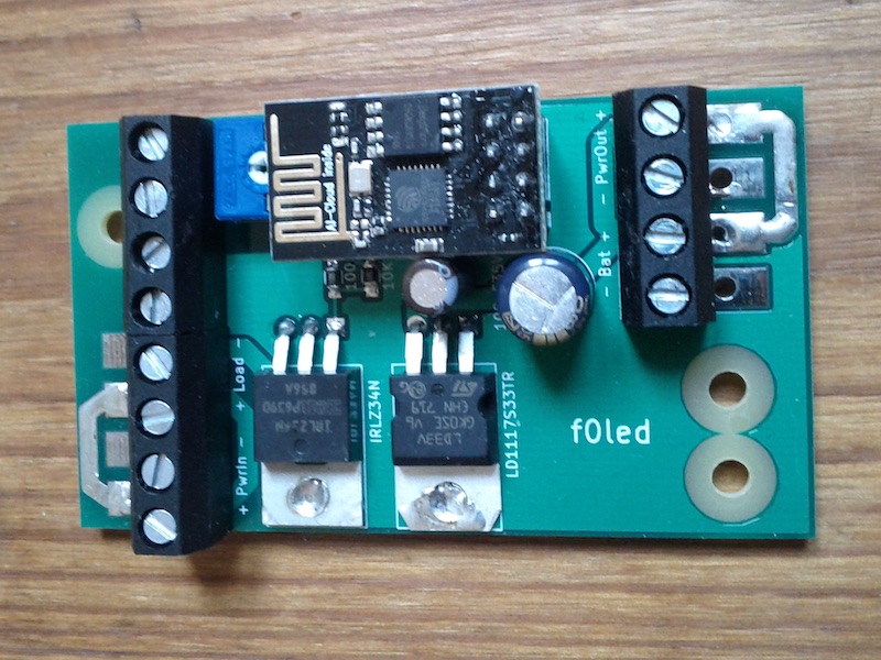
The circuit takes in 5V and then the regulator steps this down to 3.3V. Notice the huge 220uF capacitor that's needed to provide power for the ESP8266 during its infamous current draw spikes.
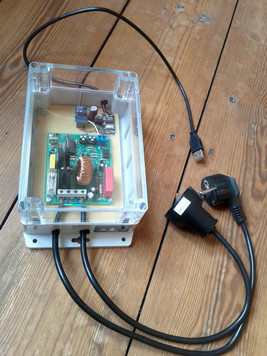
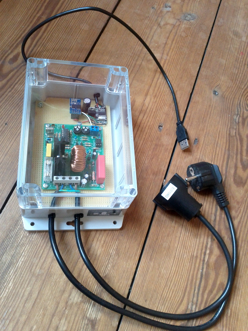
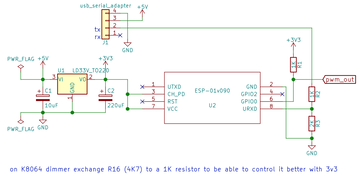
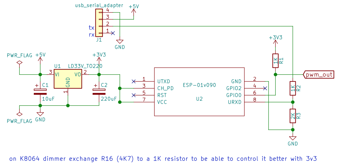
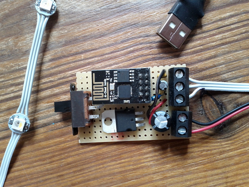
This simple addition/hack lets me control the Velleman K8064 DC dimmer kit via wireless OSC or serial. It's based on an ESP8266. The kit is isolated, can dim 220V/110V and is rated for up to 750W loads.
Normally one control it using 0-12V but by replacing a resistor (R16) it's possible to do it with the 0-3.3V PWM signal that the ESP outputs.
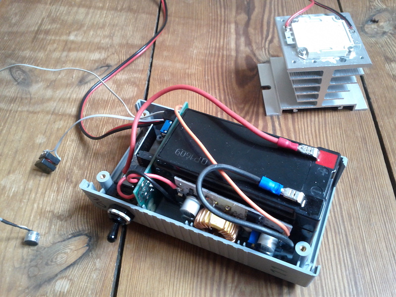
f0dim box
I probably should cut some air ventilation holes, but so far it hasn't gotten hot inside.
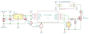
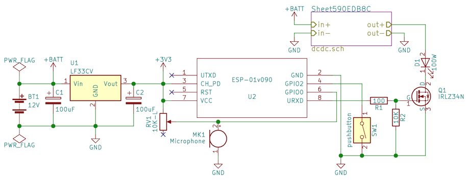
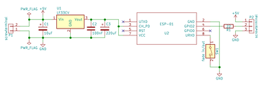
f0dim circuit schematics
Arduino code for the ESP8266...
//f.olofsson2017

// * install OSC from https://github.com/CNMAT/OSC
// * edit where it says EDIT below
// * choose board: "Generic ESP8266 Module" 160 MHz

//OSC protocol: /dim PWM fade
//  PWM should be 0.0-1.0
//  fade should be 0.0-1.0 (1.0=instant)
//serial protocol: 253 254 PWMhi PWMlo fadehi fadelow 255
//  PWM hi and lo should be 0-1023
//  fade hi and lo should be 0-1023 (1023=instant)

#include <ESP8266WiFi.h>
#include <WiFiUdp.h>
#include <OSCMessage.h>

#define PORT 15551  //receiving OSC port
#define PINPWM 0
#define PAYLOAD 4
#define UPDATERATE 16
#define TRIES 100  //how many times try check for wifi connection at startup

const char *ssid = "wifinetwork"; //EDIT your accessPoint network name
const char *password = "wifipassword";  //EDIT your password
const char *espname = "f0dim";
WiFiUDP Udp;
bool wifi;

byte serial_index = 0;
byte serial_data[PAYLOAD];
unsigned long next_time;
float dim = 0.0, dim_target = 0.0, dim_fade = 1.0;

void setup() {
  analogWriteFreq(5000);   //5khz pwm
  Serial.begin(115200, SERIAL_8N1, SERIAL_RX_ONLY);
  pinMode(LED_BUILTIN, OUTPUT);
  pinMode(PINPWM, OUTPUT);
  analogWrite(PINPWM, 0);
  delay(10);
  WiFi.mode(WIFI_STA);
  WiFi.hostname(espname);
  WiFi.begin(ssid, password);
  byte cnt = 0;
  wifi = false;
  while ((WiFi.status() != WL_CONNECTED) && (cnt < TRIES)) {
    delay(100);
    cnt++;
    digitalWrite(LED_BUILTIN, cnt % 2);
  }
  if (WiFi.status() == WL_CONNECTED) {
    Udp.begin(PORT);
    wifi = true;
  }
  digitalWrite(LED_BUILTIN, !wifi); //blue led on if connected to wifi
}

void oscDim(OSCMessage &msg) {
  dim_target = msg.getFloat(0);
  dim_fade = msg.getFloat(1);
}

void loop() {

  //--serial input
  while (Serial.available() > 0) {
    byte val = Serial.read();
    if ((serial_index == 0) && (val == 253)) {
      serial_index = 1;
    } else if ((serial_index == 1) && (val == 254)) {
      serial_index = 2;
    } else if ((serial_index >= 2) && (serial_index < (PAYLOAD + 2))) {
      serial_data[serial_index - 2] = val;
      serial_index++;
    } else if ((serial_index == (PAYLOAD + 2)) && (val == 255)) {
      dim_target = ((serial_data[0] << 8) + serial_data[1]) / 1023.0;
      dim_fade = ((serial_data[2] << 8) + serial_data[3]) / 1023.0;
      serial_index = 0;
    } else {
      serial_index = 0;
    }
  }

  //--OSC input
  if (wifi) {
    int packetSize = Udp.parsePacket();
    if (packetSize) {
      OSCMessage oscMsg;
      while (packetSize--) {
        oscMsg.fill(Udp.read());
      }
      if (!oscMsg.hasError()) {
        oscMsg.dispatch("/dim", oscDim);
      }
    }
  }

  //--fading
  if (millis() >= next_time) {
    next_time = millis() + UPDATERATE;
    if (dim < dim_target) {
      dim = dim + dim_fade;
      if (dim > dim_target) {
        dim = dim_target;
      }
    } else if (dim > dim_target) {
      dim = dim - dim_fade;
      if (dim < dim_target) {
        dim = dim_target;
      }
    }
    analogWrite(PINPWM, int(dim * 1023));
  }
}
SuperCollider example code...
//f0dim can be controlled either via OSC or serial
n= NetAddr("192.168.1.105", 15551);
n.sendMsg(\dim, 1.0, 1.0);  //set 100% instantly
n.sendMsg(\dim, 0.5, 1.0);  //set 50% instantly
n.sendMsg(\dim, 0.0, 1.0);  //set 0% instantly
n.sendMsg(\dim, 1.0, 0.001);  //slow fade in
n.sendMsg(\dim, 0.0, 0.0005);  //slower fade out

SerialPort.listDevices;
(
~port= SerialPort("/dev/tty.usbserial123", 115200, crtscts: true);  //EDIT serialport
CmdPeriod.doOnce({~port.close});
f= {|pwm= 1023, fade= 1023|
  Int8Array[253, 254, pwm>>8, pwm%256, fade>>8, fade%256, 255];
};
)

~port.putAll(f.value(1023, 1023));  //set 100% instantly
~port.putAll(f.value(512, 1023));  //set 50% instantly
~port.putAll(f.value(0, 1023));  //set 0% instantly
~port.putAll(f.value(1023, 3));  //slow fade in
~port.putAll(f.value(0, 2));  //slower fade out

~port.close;
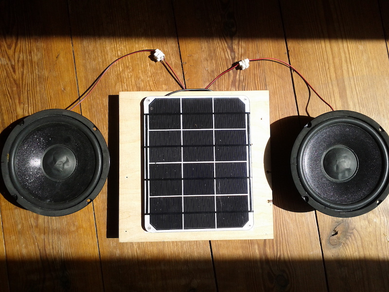
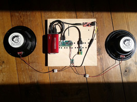
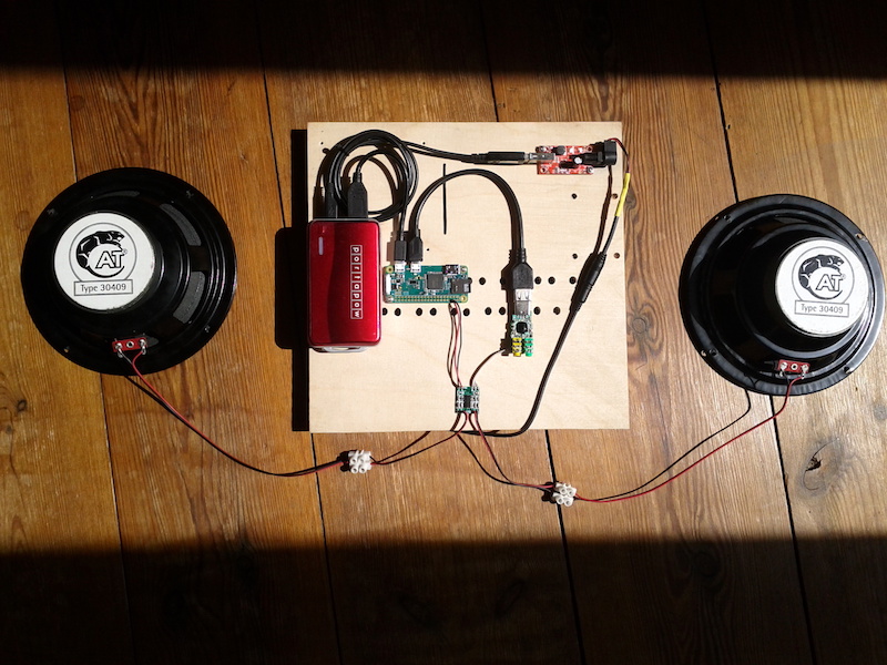
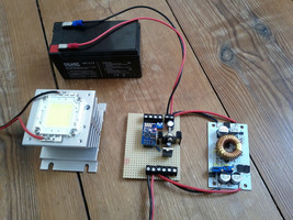
Here's how to run SuperCollider on power coming from the sun...
The main component is a Raspberry Pi Zero with WiFi that at startup creates a wireless access point, starts jackd+SuperCollider and launches a default sound patch.
To play around with the system and change the default sound log on to the access point with a laptop and start live coding SuperCollider via the terminal or use the standard SC-IDE via VNC. One can for example also set up a couple of OSC responders and let friends log on with their phones to control sounds.
The DC-DC converter is taking the higher voltage coming out of the solar panel (~6V) and turns it into a stable 5V. This is then either charging the battery, or directly powering the Raspberry Pi Zero. Note that the amplifier also needs 5V and here I have taken that from pins 4 and 6 on the RPi.
The power bank battery is optional and can be omitted but then the solar panel will have to stay in the sun at all times - else the system will turn off or reboot when the power from the panel drops. The battery acts as a reservoir for when clouds are passing by but not only that - it also lets the system be used for a couple of hours in the evening.
Material/modules needed:
RPi Zero W
8GB micro SD card
5V USB power bank (best if it can charge and output power at the same time)
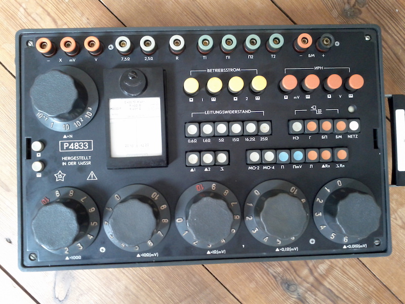
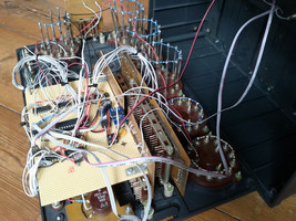
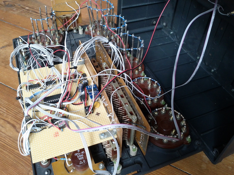
After many years I finally got around to rebuild one of these boxes.
So this old Soviet-made device is now a wireless controller that send out OSC. There are in total 34 buttons, 16 knobs and an additional RGB status led. It automatically connects via WiFi to MaxMSP or SuperCollider and runs on 5V (USB power bank).
This box can drive eight speakers (3 Watt each) and play sound files independently from eight micro SD cards (MP3 or Wav). An Arduino Nano is programmed to do sequencing, randomise playback, control volume and set equaliser settings. It all runs on a single 9-12V power supply.
f08ch box
Very cheap to build. The biggest cost is all the SD cards.
To send commands out to all eight MP3 players, I'm bit banging 9600 baud serial data out on eight digital pins.
Here is another project built around the ESP8266. It's a wireless OSC controlled 100W led. As the led should act as a stroboscope and not be kept on for long durations of time, I could save space and cost using a smaller sized heatsink. Via WiFi and OSC (Open Sound Control) the led can be turned on/off, the level, attack and release times adjusted etc. There is also a push-button trigger input as well as a microphone input. So the strobe can be either triggered manually by the musician, by the sound of the nearby instrument or remotely by a computer.
The strobe also sends out OSC data from the button and mic so it can, in turn, be used to trigger additional sounds in the computer.
Here is how I build super cheap wireless OSC controlled RGB led strips. The main components for these are an ESP8266, a 5V power bank, a voltage regulator and some LEDs. The LEDs I've used so far are the SK6812 RGBW, but it is easy to adapt the Arduino code to work with other models like the WS2812B.
f0neo schematics
A basic version of the Arduino code shown here below. When it starts it creates a soft access point. Connect to it with a computer or phone, figure out the IP address of the ESP8266 and start sending OSC commands to it.
// * install OSC from https://github.com/CNMAT/OSC
// * install Adafruit_NeoPixel from library manager
// * edit where it says EDIT below
// * choose board: "Generic ESP8266 Module"
// * upload and connect to softap with laptop
// * try to send OSC messages to ip 192.168.4.1 port 19999
//protocol: [\rgbw, index, red, green, blue, white] example red: [\rgbw, 0, 255, 0, 0, 0]

#include <ESP8266WiFi.h>
#include <WiFiUdp.h>
#include <OSCMessage.h>
#include <OSCData.h>
#include <Adafruit_NeoPixel.h>

#define PORT 19999
#define NUMNEO 12  //EDIT number of neo pixels in use
#define PINNEO 2

const char *ssid = "f0neo"; //EDIT softAccessPoint network name
const char *password = "mypass123";  //EDIT password

WiFiUDP Udp;

//EDIT to match type of LEDs (see example/Adafruit_NeoPixel/strandtest)
Adafruit_NeoPixel pixels = Adafruit_NeoPixel(NUMNEO, PINNEO, NEO_RGBW + NEO_KHZ800);

void setup() {
  pixels.begin();
  pixels.show();
  WiFi.mode(WIFI_AP);
  WiFi.softAP(ssid, password);
  Udp.begin(PORT);
}

void rgbw(OSCMessage &msg) {
  pixels.setPixelColor(msg.getInt(0), msg.getInt(2), msg.getInt(1), msg.getInt(3), msg.getInt(4));
  pixels.show();
}

void loop() {
  OSCMessage oscMsg;
  int packetSize = Udp.parsePacket();
  if (packetSize) {
    while (packetSize--) {
      oscMsg.fill(Udp.read());
    }
    if (!oscMsg.hasError()) {
      oscMsg.dispatch("/rgbw", rgbw);
    }
  }
}
Attached (zip file) are more elaborate versions of this code - also including MaxMSPJitter and SuperCollider examples and KiCad schematics.