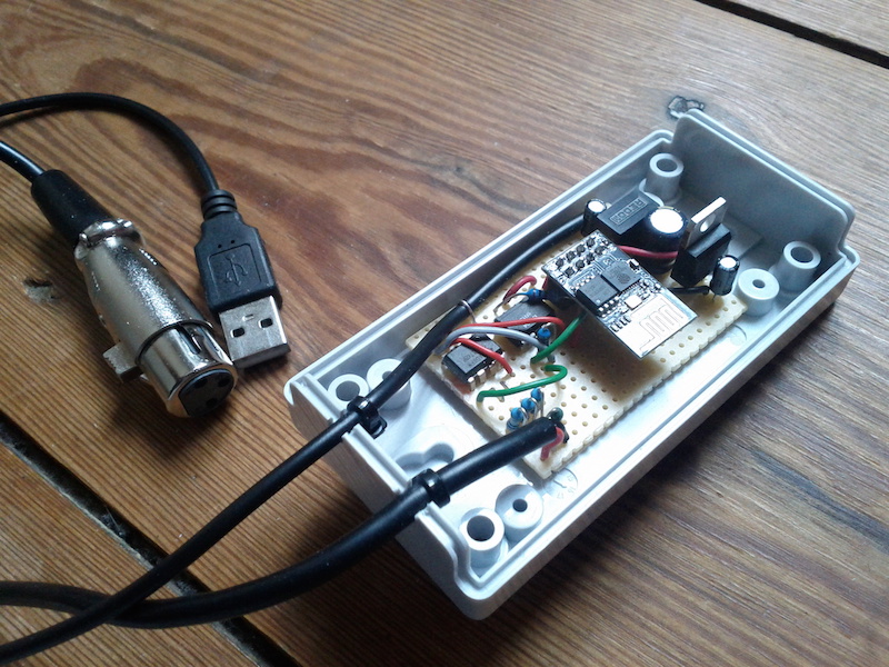
Here is how I built a wireless isolated DMX controller that takes OSC input. The box uses an ESP8266 to create a WiFi access point that one can connect to with a laptop (or phone or whatever). Open Sound Control messages sent to the box are converted into standard DMX commands. Multiple clients can be connected and send DMX commands at the same time.
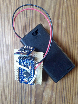
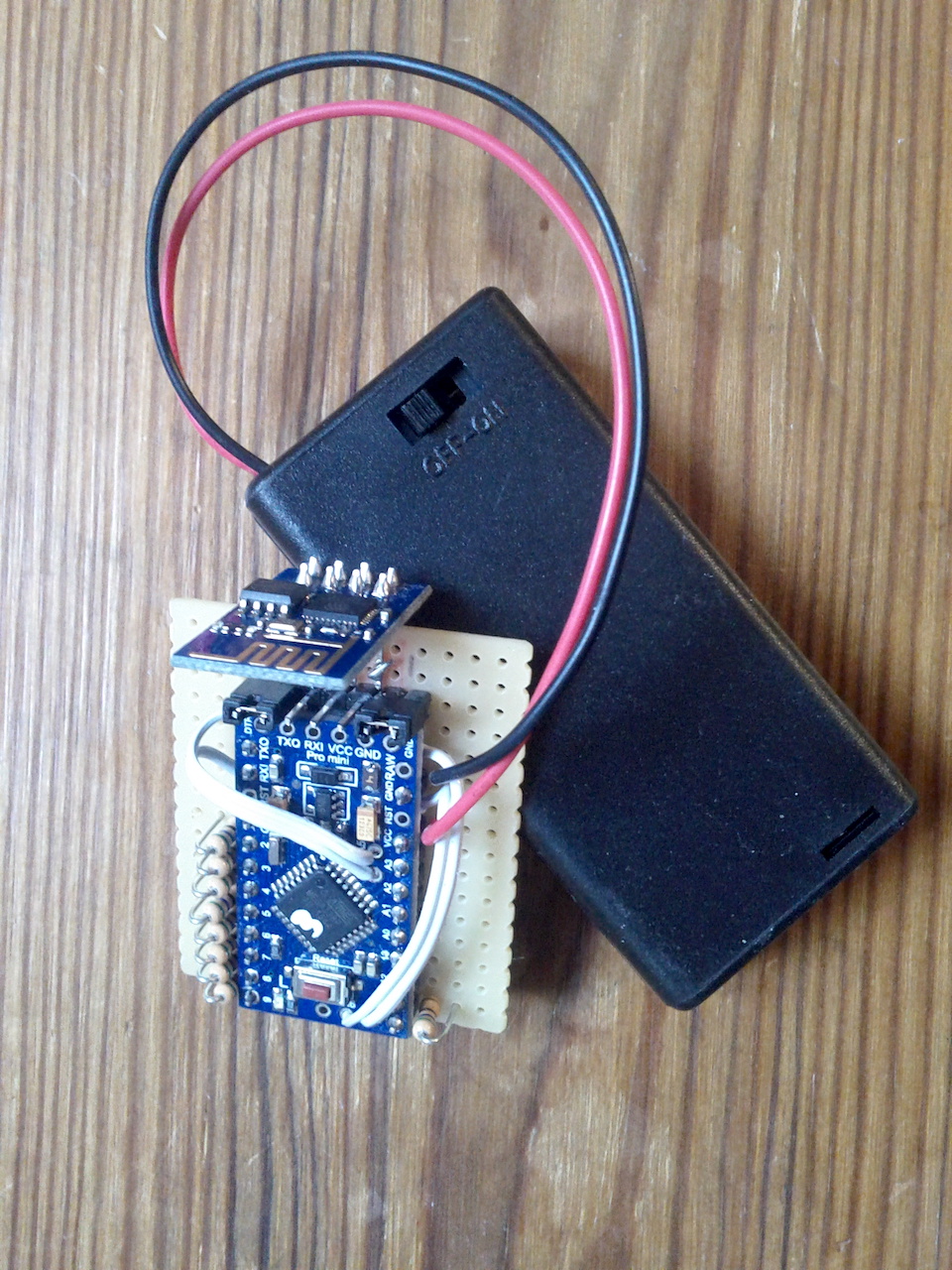
inside f0dmx box
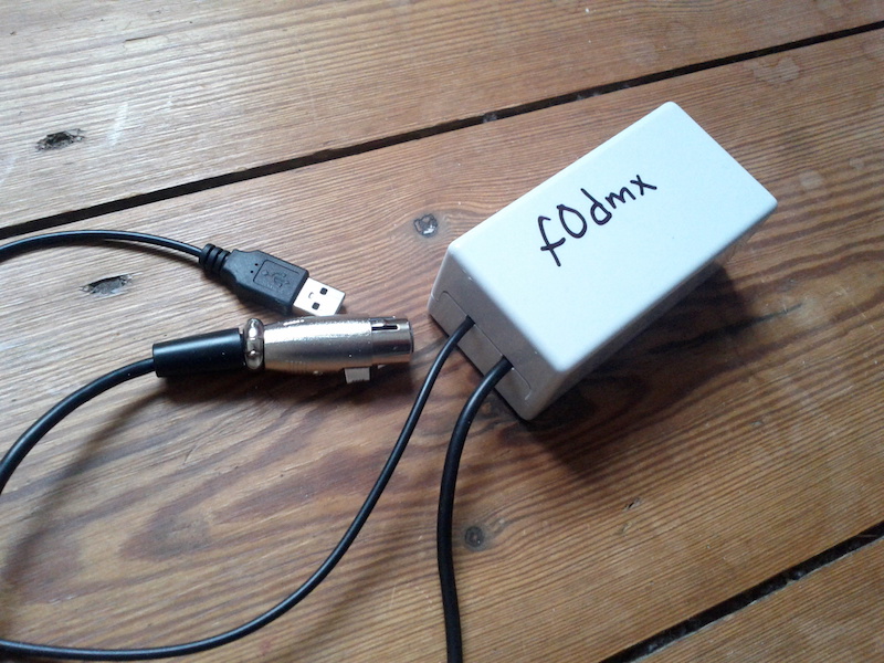
f0dmx box
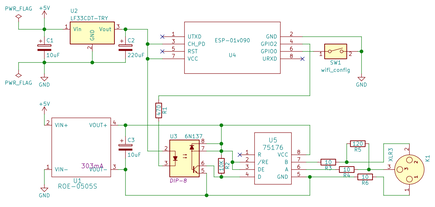
Below is Arduino code for the ESP8266, Bill-Of-Material, the KiCad schematics and some SuperCollider test code.
// * install OSC from https://github.com/CNMAT/OSC
// * install WiFiManager from https://github.com/tzapu/WiFiManager
// * install LXESP8266UARTDMX from https://github.com/claudeheintz/LXESP8266DMX
// * select board: "Generic ESP8266 Module" 160 MHz

#include <ESP8266WiFi.h>
#include <DNSServer.h>
#include <ESP8266WebServer.h>
#include <ESP8266mDNS.h>
#include <Ticker.h>
#include <WiFiManager.h>
#include <WiFiUdp.h>
#include <OSCMessage.h>
#include <OSCData.h>
#include <LXESP8266UARTDMX.h>

#define CONFIG_PIN 0  //GPIO0 to GND to reset WiFi
#define PORT 19998  //EDIT OSC input port
#define OUTPORT 57120  //EDIT OSC output port (only used at startup for announcement)
const char *espname = "f0dmx";

Ticker ticker;
IPAddress outIp;
WiFiUDP Udp;

void setup() {
  delay(10);
  pinMode(CONFIG_PIN, INPUT);
  pinMode(LED_BUILTIN, OUTPUT);
  ticker.attach(0.6, tick);

  WiFi.hostname(espname);
  wifi_station_set_hostname(espname);
  WiFiManager wifiManager;
  wifiManager.setAPCallback(configModeCallback);
  if (!wifiManager.autoConnect(espname)) {
    ESP.reset();
    delay(1000);
  }
  MDNS.begin(espname);  //make .local work
  outIp = WiFi.localIP();
  Udp.begin(PORT);
  OSCMessage msg("/ready");  //announcement
  msg.add(espname);
  msg.add(int(outIp[0]));
  msg.add(int(outIp[1]));
  msg.add(int(outIp[2]));
  msg.add(int(outIp[3]));
  msg.add(PORT);
  outIp[3] = 255;  //use broadcast IP x.x.x.255
  Udp.beginPacket(outIp, OUTPORT);
  msg.send(Udp);
  Udp.endPacket();
  yield();
  msg.empty();

  ESP8266DMX.startOutput();

  ticker.detach();
  digitalWrite(LED_BUILTIN, LOW);  //debug
}

void tick() {
  int state = digitalRead(LED_BUILTIN);
  digitalWrite(LED_BUILTIN, !state);  //debug
}
void configModeCallback(WiFiManager *myWiFiManager) {
  ticker.attach(0.15, tick);
}

void dmx(OSCMessage &msg) {
  int chan, value;
  for (byte i = 0; i < msg.size(); i = i + 2) {
    chan = getIntCast(msg, i);
    value = getIntCast(msg, i + 1);
    ESP8266DMX.setSlot(chan, value);
  }
}

int getIntCast(OSCMessage &msg, int index) {  //support for both integers and floats
  if (msg.isInt(index)) {
    return msg.getInt(index);
  }
  return int(msg.getFloat(index));
}

void start(OSCMessage &msg) {
  ESP8266DMX.startOutput();
}

void stop(OSCMessage &msg) {
  ESP8266DMX.stop();
}

void loop() {
  OSCMessage oscMsg;
  int packetSize = Udp.parsePacket();
  if (packetSize) {
    while (packetSize--) {
      oscMsg.fill(Udp.read());
    }
    if (!oscMsg.hasError()) {
      oscMsg.dispatch("/dmx", dmx);
      oscMsg.dispatch("/start", start);
      oscMsg.dispatch("/stop", stop);

      tick();
    }
  }

  //--wifi
  if (digitalRead(CONFIG_PIN) == LOW) {  //reset pin
    WiFiManager wifiManager;
    wifiManager.resetSettings();
    wifiManager.setAPCallback(configModeCallback);
    wifiManager.autoConnect(espname);
    ticker.detach();
    digitalWrite(LED_BUILTIN, LOW);  //debug
  }
}
Example of how to send OSC from SuperCollider to the f0dmx box.
//make sure you are connected to the same WiFi network as f0dmx
n= NetAddr("f0dmx.local", 19998);  //the IP and port of the f0dmx box
n.sendMsg(\dmx, 9, 255);  //dmx channel 9, value 255
n.sendMsg(\dmx, 9, 0);
n.sendMsg(\dmx, 7, 100);  //dmx channel 7, value 100
n.sendMsg(\dmx, 7, 0);

n.sendMsg(\stop);  //usually not needed
n.sendMsg(\start);
Updates:
180620: cast floats to integers (getIntCast), increased electrolytic cap value from 100 to 220uF
181212: simplified WiFi setup with the WiFiManager library
+2 years ago I put up a simple example of how to use firmata with Arduino and SuperCollider. See /f0blog/supercollider-firmata/. That code still works but it only shows how to read a single analogue input on the Arduino.
Here is how one can read both A0 and A1 and map those to synth parameters in SuperCollider...
//how to read pins A0 and A1 with SCFirmata...
//tested with Arduino1.8.0 and SC3.8.0
//first in Arduino IDE:
//  * select File / Examples / Firmata / StandardFirmata
//  * upload this example to an Arduino
//then in SC install the SCFirmata classes
//  * download zip file https://github.com/blacksound/SCFirmata
//  * extract files and put them in your SC application support directory
//  * recompile SC

SerialPort.devices;
d= SerialPort.devices[0]; // or d= "/dev/tty.usbserial-A1001NeZ" - edit number (or string) to match your Arduino
f= FirmataDevice(d);//if it works it should post 'Protocol version: 2.5' after a few seconds

s.boot

(
Ndef(\snd, {|freq1= 400, freq2= 500, amp= 0.5| SinOsc.ar([freq1, freq2].lag(0.08), 0, amp.lag(0.08)).tanh}).play;
f.reportAnalogPin(0, true);  //start reading A0
f.reportAnalogPin(1, true);  //start reading A1
f.analogPinAction= {|num, val|
  [num, val].postln;
  switch(num,
    0, {
      Ndef(\snd).set(\freq1, val.linexp(0, 1023, 400, 800));  //A0 mapped to freq1
    },
    1, {
      Ndef(\snd).set(\freq2, val.linexp(0, 1023, 400, 800));  //A1 mapped to freq2
    }
  );
};
)

(
Ndef(\snd).stop;
f.reportAnalogPin(0, false);  //stop reading A0
f.reportAnalogPin(1, false);  //stop reading A1
f.end;
f.close;
)
And to read all six analogue inputs (A0-A5) one can do...
SerialPort.devices;
d= SerialPort.devices[0]; // or d= "/dev/tty.usbserial-A1001NeZ" - edit number (or string) to match your Arduino
f= FirmataDevice(d);//if it works it should post 'Protocol version: 2.5' after a few seconds

s.boot
~numberOfAna= 6;  //number of analogue inputs (here A0-A5)

(
var freqsArr= 0!~numberOfAna;
Ndef(\snd2, {|amp= 0.5| Splay.ar(SinOsc.ar(\freqs.kr(freqsArr, 0.05), 0, amp.lag(0.08)).tanh)}).play;
~numberOfAna.do{|i|
  f.reportAnalogPin(i, true);  //start reading A0-Anum
};
f.analogPinAction= {|num, val|
  [num, val].postln;
  freqsArr.put(num, val);
  Ndef(\snd2).setn(\freqs, freqsArr);
};
)

(
Ndef(\snd2).stop;
~numberOfAna.do{|i|
  f.reportAnalogPin(i, false);  //stop reading A0-Anum
};
f.end;
f.close;
)
I've started using MQTT for talking to microcontrollers over WiFi and here's some code and instructions on how to set up such a system.
There are two programs that have to run in the background. They handle all the communication between the wireless hardware and the client software (MaxMSPJitter, SuperCollider etc). One is Mosquitto. Mosquitto is a MQTT broker and the central pub/sub hub of the system. The second program is a Python MQTT-OSC bridge script using the Paho client. This Python script lets programs like MaxMSPJitter or SuperCollider talk to Mosquitto via OSC. See the readme.txt included below on how to install and configure these programs.
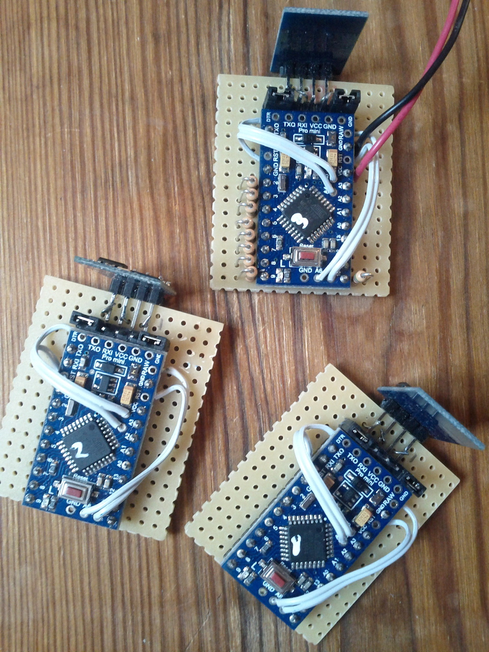
On the hardware side, I build send/receive circuit nodes consisting of an ESP8266-01 module and an Arduino Pro Mini. These circuits run on 3V, are small and configurable and the parts cost almost nothing. The ESP8266 module provides WiFi communication and runs a MQTT client (I'm using the Adafruit MQTT library), while the Pro Mini does the physical inputs and outputs (sensors, LEDs etc). The two modules talk to each other via serial.
Some circuits I've built do 12 digital + 8 analogue inputs, while others have 12 LEDs in combination with 8 analogue inputs. But any combination is possible and the number of ins/outs depends on how the Pro Mini is programmed. (See portable_promini_ana and portable_promini_led in the zip archive below.)
So far I'm really pleased with this new technique. It seems to scale well and work more reliable than what I used before (sending raw OSC via CC3000 or ESP8266).
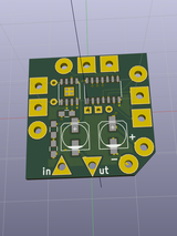
I got to design and build version 2 of Syntjuntan's sewable synthesizer circuit. For this version, they wanted to add an on-board amplifier that could drive a passive speaker element.
The circuit now has three Schmitt triggers and can run on 3-12V. The amplifier is the classic LM386 and the connector pads around the board are made to fit needle and conductive thread as well as being crocodile friendly.
There are some options as standard through-hole soldering pads (a fourth Schmitt trigger and x10 extra gain). The circuit can also be used as a standalone audio amplifier - just ignore the Schmitt triggers and connect your own signal to the pad marked in.
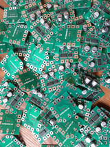
Anyway, lots of fun mass producing this and in the process I learned how to do hot-air SMD soldering with stencil and solder paste plus got to know KiCad a bit better.
I also built a test rig with an Arduino and some pogo pins. It both scans for short-cuts and tests the sound.
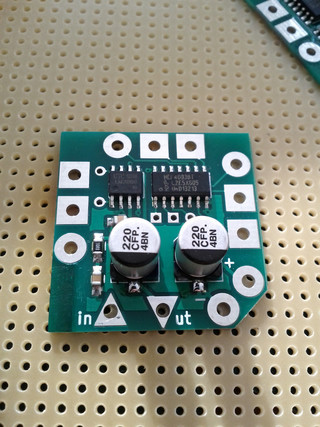
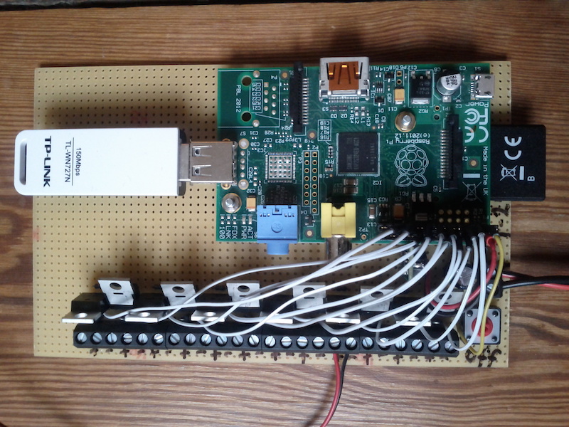
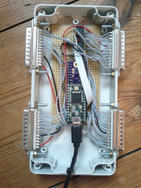
This board is using an old Raspberry Pi 1 to control the speed of computer fans. The electronics are pretty simple (see attached schematics below): it takes 7-36V input power, has twelve MOSFETs for PWM control and finally a DC-DC converter to power the RPi. It was built for controlling PC cooling fans but can also drive other types of DC motors, lightbulbs or solenoids. The off button is there to safely power down the Raspberry Pi.
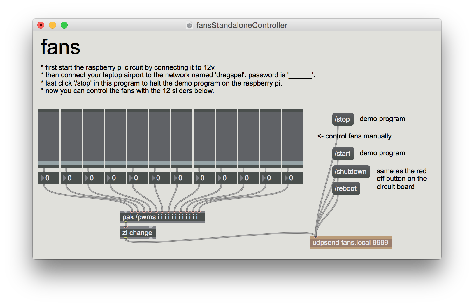
The trick with this though is that the system can be livecoded over WiFi using SuperCollider, MaxMSP or any other OSC capable program. So when you start the board the RPi sets up a wireless access point and starts a Python script that accepts incoming Open Sound Control messages. At startup, the RPi1 will also start SuperCollider and load a file (dragspelFans.scd) that is meant to contain whatever code you'd like to run as default. This file you later overwrite with your own SuperCollider code that you've developed/livecoded using your laptop.
dragspel circuit
Below are step-by-step instructions on how I set this up plus the relevant Python and SuperCollider code. It should work on all RPi models but here the RPi1 or RPi0 is assumed.
to enable SSH, create an empty file on the SD card. Call it ssh. (this terminal command touch /Volumes/boot/ssh will do it on macOS or just create an empty text file and save it without any file extension)
connect your RPi to your home router via ethernet and type the following in terminal on your laptop:
ssh-keygen -R raspberrypi.local
ssh pi@raspberrypi.local #default password is raspberry
sudo raspi-config #change password to _____, set memory split to 16 under advanced, change hostname to fans under network, update, finish and reboot (sudo reboot)
ssh pi@fans.local #log in again from your laptop
sudo apt-get update
sudo apt-get upgrade
sudo apt-get dist-upgrade
Python
This section will install OSC and GPIO libraries for Python and also set up the Python script to automatically start at system boot.
nano ~/dragspelFans.py #and copy&paste in the following:
#f.olofsson2016-2018
#pwm control for 12 fans/motors/LEDs

#NOTE: make sure to run this in terminal first...
# sudo pigpiod -s 5

import sys
from os import system
from time import sleep
import pigpio
from liblo import *

inport= 9999  #for OSC commands to this Python script
pinoff= 2  #bcm numbering
pins= [3, 4, 14, 15, 17, 18, 27, 22, 23, 24, 10, 9]  #bcm numbering - more can be added here
target= ('127.0.0.1', 57120)  #for OSC to sclang
hz= 800  #pwm frequency in hz - note may need to adapt -s option in sudo pigpio -s 5 above
range= 100  #duty cycle range 0 to 100

pi= pigpio.pi()
pi.set_mode(pinoff, pigpio.INPUT)  #no internal pullup needed
for pin in pins:
  pi.set_mode(pin, pigpio.OUTPUT)
  pi.set_PWM_frequency(pin, hz)
  pi.set_PWM_range(pin, range)
  pi.set_PWM_dutycycle(pin, 0)

class MyServer(ServerThread):
  def __init__(self):
    ServerThread.__init__(self, inport)
  @make_method('/pwms', 'i'*len(pins))
  def pwms_callback(self, path, args):
    #print args  #debug
    i= 0
    for pin in pins:
      pi.set_PWM_dutycycle(pin, min(max(0, args[i]), range))
      i= i+1
  @make_method('/shutdown', '')
  def shutdown_callback(self, path, args):
    stop('sudo halt -p')  #turn off rpi
  @make_method('/reboot', '')
  def reboot_callback(self, path, args):
    stop('sudo reboot')  #reboot rpi
  @make_method('/start', '')
  def start_callback(self, path, args):
    send(target, '/start', 1)  #start default program in SuperCollider
  @make_method('/stop', '')
  def stop_callback(self, path, args):
    send(target, '/stop', 0)  #stop default program in SuperCollider
    for pin in pins:  #and also set all pwm to 0
      pi.set_PWM_dutycycle(pin, 0)
  @make_method(None, None)
  def fallback(self, path, args):
    print 'received unknown message "%s"' % path

def stop(cmd):
  pi.stop()
  server.stop()
  system('killall pigpiod sclang')
  system(cmd)
  sleep(1)
  sys.exit()

try:
  server= MyServer()
except ServerError, err:
  print str(err)
  sys.exit()
server.start()

def main():
  while True:
    if pi.read(pinoff)==0:
      print 'shutting down...'
      stop('sudo halt -p')
    sleep(0.5)

if __name__ == '__main__':
  try:
    main()
  except KeyboardInterrupt:
    pi.stop()
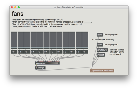
Again use ctrl+o and ctrl+x to save and exit. Now sudo reboot and then try to send OSC commands to the RPi. Here's how to send some test OSC messages from your laptop to the RPi using SuperCollider...
n= NetAddr("fans.local", 9999);
n.sendMsg(\pwms, *[50, 0, 0, 0, 0, 0, 0, 0, 0, 0, 0, 0]);  //the number of integers should match the number of pins and range in your Python code (here 12 pins, 0-100)
n.sendMsg(\pwms, *[25, 50, 75, 0, 0, 0, 0, 0, 0, 0, 0, 0]);  //first pin 25%, second %50 third 75%, rest 0
n.sendMsg(\pwms, *[0, 0, 0, 0, 0, 0, 0, 0, 0, 0, 0, 0]);  //all off
You can also try to connect pin bcm2 to ground. That should now act like an off button and turn off the RPi in a safe way.
SuperCollider
This section is optional. Only install SuperCollider if you want to run your RPi as a standalone installation or something similar. So if you plan to always remote control the system you can skip over this step.
Note: this is for RPi0&RPi1, for RPi2&RPi3 change all references to supercolliderStandaloneRPI1 below to supercolliderStandaloneRPI2
nano share/user/Extensions/DragspelFans.sc #and copy&paste in the following:
//f.olofsson2016-2018 - for controlling 12ch computer fan switch board
DragspelFans {
  var <rpi, num, vals, lastv, <>debug;
  *new {|debug= false, rpi, num= 12|
    ^super.new.initDragspelFans(debug, rpi, num);
  }
  initDragspelFans {|d, r, n|
    num= n;
    if(r.notNil, {
      rpi= r;
    }, {
      try{
        rpi= NetAddr("fans.local", 9999);
      } {|err|
        "could not connect to rpi.\n make sure you are connected to the wifi network 'dragspel'.".warn;
        rpi= NetAddr("127.0.0.1", 9999);  //temp just for testing
      };
    });
    debug= d;
    vals= 0!num;
  }

  setAll {|val= 100|  //val should be 0 to 100
    vals= val!num;
    this.prSend;
  }
  clearAll {
    vals= 0!num;
    this.prSend;
  }
  val {|index, val|  //index should be 0-11, val 0-100
    vals= vals.put(index, val);
    this.prSend;
  }
  arr {|arr|  //arr should be 12 numbers in an array
    vals= arr;
    this.prSend;
  }

  shutdown {
    rpi.sendMsg(\shutdown);
  }
  reboot {
    rpi.sendMsg(\reboot);
  }
  start {
    rpi.sendMsg(\start);
  }
  stop {
    rpi.sendMsg(\stop);
  }

  //--private
  prSend {|v|
    if(debug, {
      vals.postln;
    });
    v= vals.clip(0, 100).round.asInteger;
    if(v!=lastv, {  //filter out repeats
      lastv= v;
      rpi.sendMsg(\pwms, *v);  //send to dragspelFans.py
    });
  }
}
nano ~/dragspelFans.scd #and copy&paste in the following:
//demo autostart script - put your own standalone code in here
d= DragspelFans.new;
Event.addEventType(\fans, {d.val(~index, ~val)});
Pbind(\type, \fans, \dur, 0.5, \index, Pseq([0, 1, 2, 3, 4, 5, 6, 7, 8, 9, 10, 11], inf), \val, Pwhite(0, 100, inf)).play;
crontab -e #and add the following to the end (note no sudo here this time)
@reboot cd /home/pi/supercolliderStandaloneRPI1 && xvfb-run ./autostart.sh
Now sudo reboot and SuperCollider should automatically start the code in dragspelFans.scd. It'll take a while so give it a minute or two.
To test it more run the following SuperCollider code on your laptop...
n= NetAddr("fans.local", 9999);
n.sendMsg(\stop);  //first stop the dragspelFans.scd script
n.sendMsg(\pwms, *[25, 50, 75, 0, 0, 0, 0, 0, 0, 0, 0, 0]);  //set pwm manually

//install the DragspelFans.sc class on your laptop SC and also try the following example code

a= DragspelFans(true);  //might take a moment or two
CmdPeriod.doOnce({a.clearAll});  //optional

//version0 - all on or off
a.setAll;
a.clearAll;
a.setAll(50);  //set all to some value 0-100
a.clearAll;

//version1 - using an array
a.arr([0, 0, 100, 0, 0, 100, 0, 0, 100, 0, 0, 100]);  //turn on some
a.arr([0, 100, 0, 0, 100, 0, 0, 100, 0, 0, 100, 0]);  //turn some other fans
a.arr([30, 0, 0, 40, 100, 0, 40, 0, 0, 80, 0, 0]);  //a few slower
a.clearAll;

//version2 - set index to value
a.val(9, 100);
a.val(9, 0);
a.val(11, 100);
a.val(11, 0);
a.val(11, 60);
a.val(11, 0);

//fade in each fan in order
(
r= Routine.run({
  12.do{|j|
    100.do{|i|
      a.val(j, i);
      0.05.wait;
    };
    100.do{|i|
      a.val(j, 99-i);
      0.05.wait;
    };
  };
});
)
r.stop;

//using patterns
a= DragspelFans.new;
Event.addEventType(\fans, {a.val(~index, ~val)});
Pdef(\test, Pbind(\type, \fans, \dur, 0.125, \index, Pseq([0, 1, 2, 3, 4, 5, 6, 7, 8, 9, 10, 11].scramble, inf), \val, Pwhite(0, 100, inf))).play;
Pdef(\test).stop;

a.start;  //start the dragspelFans.scd script on the rpi again
a.stop;
a.reboot;
a.shutdown;


