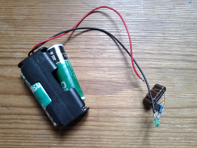
To make something useful out of 'dead' batteries I've been building Joule thief circuits. These circuits are very easy, cheap and fun to build plus it gives me a little bit less bad conscious when going to the recycling bin with the batteries. Watch this BigClive video to learn more.
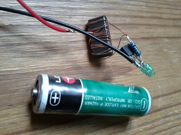
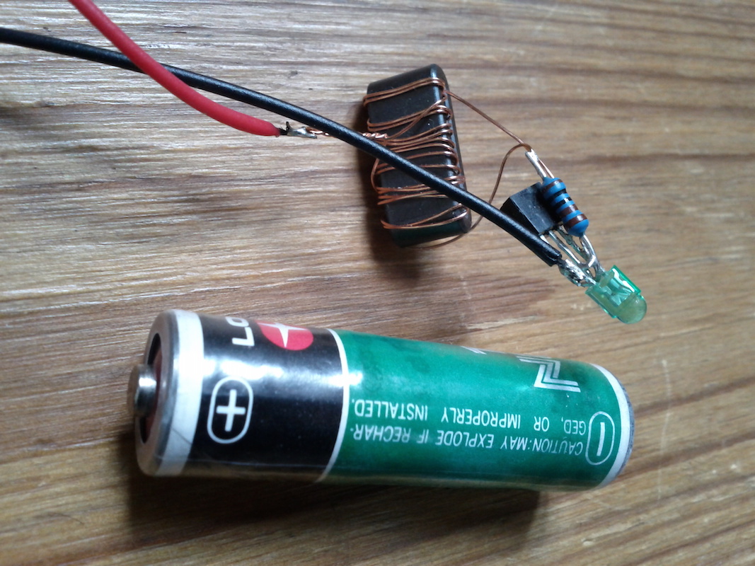
Below are pictures of one variant. It has a small 3mm green led (salvaged from a broken printer), a hand-wound coil, a resistor and a transistor.
The batteries here came with my first ever (analogue) multimeter. They are 32 years old!. See the date code: 84-04. They still can drive the little led. Amazing. I think running this little green led is a good way to use the last energy stored in these beautiful and truly long-life batteries.
Here some example Arduino code for sending and receiving OSC via the cheap ESP8266 serial WiFi module.
Note that the Open Sound Control messages here are very basic - only 4 bytes packed into a single 32bit integer.
upload the code below to an Arduino.
connect ESP8266 TX pin to Arduino pin0.
connect ESP8299 RX to Arduino pin1. It is safest to use a 3V3 lever converter for this line (or at least a voltage divider).
power the ESP8266 (VCC and GND) from an external 3V source. Do not use the Arduino 3V3 pin as it cannot provide the required current. I used an LF33CV voltage regulator to get 3.3V from the 5V supply that also powers the Arduino.
connect ESP8288 RESET pin to Arduino pin4.
and last, connect ESP8266 CH_PD to 3V3
Optional: connect a separate USB-Serial (FTDI) chip to Arduino pins 2 and 3 to use software serial debugging. Start debugging in a terminal with something like screen /dev/tty.usbserial-A4015TKA 115200
The Arduino code sits and waits for an incoming OSC message (/tap). It then replies by sending out a counter-message (/sti).
//f0 150705
//sending and receiving UDP OSC with an ESP8266
//for an Arduino + ESP8266 with firmware 0.9.5.2

#include <SoftwareSerial.h>

#define WLAN_SSID  "SSID"
#define WLAN_PASS  "PASS"
#define WLAN_ADDR  "192.168.1.51" //laptop running sc
#define PORT  1112 //incoming OSC port
String tag = "/tap"; //incoming OSC addy

SoftwareSerial mySerial(2, 3);

uint8_t buf[16];
byte cnt;
byte id, on, hi, lo;
boolean resp;

void setup() {

  //--OSC message
  buf[0] = 47;   // /
  buf[1] = 115;  // s
  buf[2] = 116;  // t
  buf[3] = 105;  // i
  buf[4] = 0;
  buf[5] = 0;
  buf[6] = 0;
  buf[7] = 0;
  buf[8] = 44;   // ,
  buf[9] = 105;  // i
  buf[10] = 0;
  buf[11] = 0;
  buf[12] = 4;   // a high   (id)
  buf[13] = 3;   // a low    (on)
  buf[14] = 2;   // b high   (hi)
  buf[15] = 0;   // b low    (lo)

  mySerial.begin(115200);
  Serial.begin(115200);
  Serial.setTimeout(10000);
  mySerial.println("");
  mySerial.println("starting");

  mySerial.print("hard reset...");
  digitalWrite(4, 0);
  pinMode(4, OUTPUT);
  delay(10);
  pinMode(4, INPUT);
  resp = Serial.find("ready\r\n");
  mySerial.println(resp);

  mySerial.print("mode1...");
  Serial.println("AT+CWMODE=1");
  resp = Serial.find("OK\r\n");
  mySerial.println(resp);

  mySerial.print("connecting...");
  do {
    Serial.print("AT+CWJAP=\"");
    Serial.print(WLAN_SSID);
    Serial.print("\",\"");
    Serial.print(WLAN_PASS);
    Serial.println("\"");
    resp = Serial.find("OK\r\n");
    mySerial.println(resp);
  } while (!resp);

  mySerial.print("mux1...");
  Serial.println("AT+CIPMUX=1");
  resp = Serial.find("OK\r\n");
  mySerial.println(resp);

  mySerial.print("udp...");
  Serial.print("AT+CIPSTART=4,\"UDP\",\"");
  Serial.print(WLAN_ADDR);
  Serial.print("\",57120,");
  Serial.print(PORT);
  Serial.println(",0");
  resp = Serial.find("OK\r\n");
  mySerial.println(resp);

  Serial.setTimeout(1000);
}
void loop() {
  while (Serial.available()) {
    String abc = Serial.readStringUntil('\n');
    if (abc.startsWith("+IPD,4,16:" + tag)) {
      id = abc[22];
      on = abc[23];
      hi = abc[24];
      lo = abc[25];
      mySerial.print("id:");
      mySerial.println(id);
      mySerial.print("on:");
      mySerial.println(on);
      mySerial.print("hi:");
      mySerial.println(hi);
      mySerial.print("lo:");
      mySerial.println(lo);

      buf[15] = cnt++;
      Serial.println("AT+CIPSEND=4,16");
      Serial.find(">");
      Serial.write(buf, sizeof(buf));
      resp = Serial.find("OK\r\n");
      mySerial.print("send...");
      mySerial.println(resp);
    }
  }
}
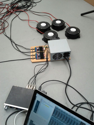
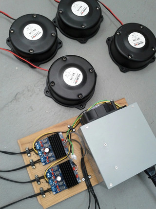
For a project in collaboration with Stine Janvin Motland I built this 4-channel transducer bass shaker system.
The system has four transducers (Visaton bs 130, 4Ω), two class D stereo amplifiers (2x50W, TDA7492 chip) and a powerful ATX switching power supply (Codecom pm-350c).
I modified the power supply to only give out 12V (yellow&black cables) and also made it start up automatically by shorting the green cable (PS-ON) to ground (black).
There's no volume control so better take care - the system is very hot.
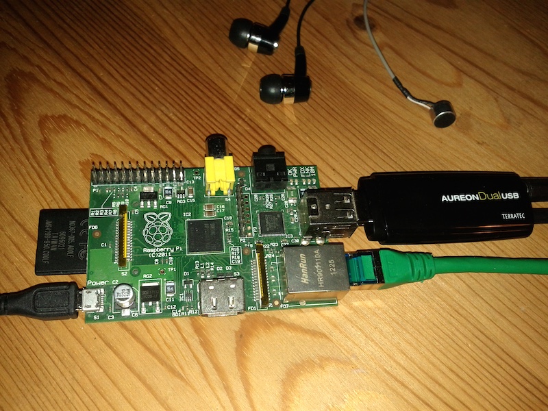
Here is a quick tutorial on how to install and run Pure Data headless on a Raspberry Pi. The instructions assume you want to start with a new clean Raspbian system image and do it all from scratch.
The instructions also assume you have a Raspberry model B, a USB soundcard like Terratec's Aureon Dual USB and an ethernet cable with internet access (just connect the ethernet cable between your RPi and your home router).
What you get after following the below tutorial is an SD card with a Pd patch that automatically starts when the RPi is booted.
Preparations
Put the Raspbian image onto a +4GB SD card (it is easily done with balenaEtcher).
On newer versions of Rasbian, activate SSH by creating an empty file called 'ssh' directly on the SD card
Insert the SD card+ethernet+usbsoundcard and power up the RPi
Open the terminal application on your laptop and type...
ssh pi@raspberrypi.local #password is 'raspberry'
See notes below if fail.
Setup
When successfully logged in run this on the RPi...
sudo raspi-config
and do the following system configurations...
Select expand filesystem (only needed on Wheezy and older versions of Raspbian)
Change user password
Optionally lower the GPU memory under advanced / memory split
Select finish and reboot
Log in again from laptop with your new password...
ssh pi@raspberrypi.local
sudo apt-get update #check for new updates
sudo apt-get upgrade #update any old packages
sudo apt-get dist-upgrade #update the distribution
Test sound
lsusb #should list the USB soundcard
aplay -l #should also list the soundcard
sudo speaker-test -t sine -c 2 -Ddefault:CARD=Device #should sound if headphones connected. Stop with ctrl+c
Note: this assumes that your USB soundcard name is Device - check what the aplay command posts and edit the CARD= in the line above if needed.
Install Pd
Download and install Pure Data + required packages with...
sudo apt-get install puredata
Test Pd patches
Copy the following two example Pd patches (or download the attachments below) and save them on your laptop (here assume on the desktop). To copy Pd patches just paste the cryptic text into a plain text editor and save with .pd file extension.
This is also how you can transfer more Pd patches later on.
Run Pure Data
ssh pi@raspberrypi.local #log in from laptop again
pd -stderr -nogui -verbose -audiodev 4 testsines.pd #stop with ctrl+c
pd -stderr -nogui -verbose -audiodev 4 testmic.pd #stop with ctrl+c
Note: if no sound test with different audiodev - 4 is usually the USB soundcard.
You will also need to connect headphones or speakers for the first example to work. And some kind of audio input (e.g. electret mic or line-in from an MP3 player) for the second example (testmic) patch to work.
Autostart
Here is how to start Pd and run a patch at boot...
nano autostart.sh #creates a new file. Copy the two lines below into this new file. (save and exit with ctrl+o, return, ctrl+x)

  #!/bin/bash
  pd -nogui -audiodev 4 /home/pi/testsines.pd

chmod +x autostart.sh #make the autostart.sh file executable
crontab -e #and add at the end... (again save and exit with ctrl+o, return, ctrl+x)

  @reboot /bin/bash /home/pi/autostart.sh
After rebooting (with the sudo reboot command) the sine tones patch should have started automatically.
Stopping
ssh pi@raspberrypi.local #log in from laptop once more
sudo pkill pd #stop Pd
sudo halt -p #turn off the RPi safely
Notes
If you cannot log in and you get ssh: Could not resolve hostname raspberrypi.local, you might need to replace raspberrypi.local with the exact IP address of the RPi (e.g. ssh pi@192.168.1.51). The exact address will vary and can be found in your router setup.
Note: if you get WARNING: REMOTE HOST IDENTIFICATION HAS CHANGED! then run the command ssh-keygen -R raspberrypi.local to reset the SSH key.
When ready with everything and you have the correct Pd patch autostarting you can (on the older RPi models with a full-sized SD card) physically lock the SD card. This will put it in no-write mode and possibly prolong its life (especially if you cut the power without properly turning off the system with sudo halt
If you experience audio dropouts you might try the suggestions here. Most important force USB1.1 and set CPU governor to performance mode.
If you get ALSA output error Device or resource busy when trying to start Pd, then delay the ;pd dsp 1 message in your Pd patch with about 100 milliseconds.
To remove the autostart just delete the file autostart.sh and go into cron again and remove the last line you added with crontab -e
Updates:
160109: also works great on a Raspberry Pi 2 with 2015-11-21-raspbian-jessie.img
180102: updated for 2017-11-29-raspbian-stretch.img and 2017-11-29-raspbian-stretch-lite.img
Just cleaned up an example for SuperCollider and Arduino that I found on my computer. It is demonstrating the SCFirmata class by Eirik Arthur Blekesaune.
//how to read pin A0 with SCFirmata...

//for Arduino1.0.6 and SC3.6.6
//first in Arduino IDE:
//  * select File / Examples / Firmata / StandardFirmata
//  * upload this example to an Arduino
//then in SC install the SCFirmata classes
//  * download zip file https://github.com/blacksound/SCFirmata
//  * extract files and put them in your SC application support directory
//  * recompile SC

SerialPort.devices
d= SerialPort.devices[0]; // or d= "/dev/tty.usbserial-A1001NeZ" - edit number (or string) to match your Arduino
f= FirmataDevice(d);//if it works it should post 'Protocol version: 2.3' after a few seconds

s.boot
Ndef(\snd, {|freq= 400, amp= 0.5| SinOsc.ar([freq, freq+4].lag(0.08), 0, amp.lag(0.08)).tanh}).play;
f.reportAnalogPin(0, true)  //start reading A0
f.analogPinAction= ({|num, val| [num, val].postln; Ndef(\snd).set(\freq, val.linexp(0, 1023, 400, 800))})//control freq
f.analogPinAction= ({|num, val| [num, val].postln; Ndef(\snd).set(\amp, val.linexp(0, 1023, 0.001, 1))})//control amp instead

Ndef(\snd).stop
f.reportAnalogPin(0, false)  //stop reading A0
f.end
f.close
Compared to generating a serial bitstream in audio, analysing and extract serial data from audio is much harder. The SuperCollider code below does it, but the program has limitations and is quite sensitive for noise.
The code takes a string, chops it up into groups of six 8bit bytes and generates a serial audio bitstream from that. Another part listens to this sound and tries to decode it. If it finds six full bytes it sends the result back to sclang via OSC where it is printed.
To test the example connect an audio cable directly from your computer's output to its input (preferably via a small mixer), or change the audioSerial SynthDef to use an internal audio bus. I can also imagine it could function with a mic next to the speakers - but I didn't test this.
If it only prints gibberish try with a different threshold setting, different volume on your computer or use a lower baud rate.
(
s.waitForBoot{
  var baudrate= 9600;
  SynthDef(\serialAudio, {|out= 0, amp= -0.5|  //for sending out serial via audio
    var data= Control.names([\data]).kr(Array.fill(60, 0));  //max 6 bytes
    var src= Duty.ar(1/baudrate, 0, Dseq(data), 2);
    OffsetOut.ar(out, src*amp);
  }).add;
  SynthDef(\audioSerial, {|in= 0, thresh= 0.05|  //for receiving serial via audio
    var raw= 0-SoundIn.ar(in);  //here change to In.ar if trying internal audio bus
    var src= raw>thresh;
    var reading= DelayC.ar(Trig1.ar(src, 1/baudrate*9), 1/baudrate/2, 1/baudrate/2);
    var osc= Phasor.ar(reading, baudrate/SampleRate.ir);
    var clock= (osc-Delay1.ar(osc))<0+Impulse.ar(0);
    var index= PulseCount.ar(clock, reading);
    var stopTrig= index>7;
    var data= Latch.ar(src, index>=#[7, 6, 5, 4, 3, 2, 1]);
    var byte= (1-data).sum{|x, i| 2**(6-i)*x};
    SendReply.ar(stopTrig, '/data', byte);
    DC.ar(0);
  }).add;
  OSCFunc({|msg| msg[3].asInteger.asAscii.post}, '/data');
  s.sync;
  Synth(\audioSerial);
};
)

(
var str= "hello supercollider!";
var baudrate= 9600;
fork{
  1.wait;
  str.ascii.clump(6).do{|bytes|
    var data= bytes.collect{|x| [1]++(1-x.asBinaryDigits.reverse)++[0]}.flat;
    s.bind{
      Synth(\serialAudio, [\data, data]);
    };
    (1/baudrate*60+0.005).wait;
  };
};
)
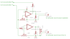
One can use this technique to communicate with another computer via audio. To communicate with a microcontroller (e.g. an Arduino), one needs additional electronics (amplification, rectification). Here's schematic for a bi-directional circuit for talking to a 5V Arduino.
This audio-to-serial technique was used to get input from RFID, touch and bend sensors in our Reflect installation i.e. SuperCollider is running on an iPod Touch and receives all sensor data via audio from an ATmega168 microcontroller.
Another way (compared to FSK in my previous blog entry) of sending data via audio is to directly generate the serial bit stream using SuperCollider.
To test and learn about these things I first wrote and uploaded a very simple program to an Arduino board. The program just transmitted the bytes 128, 10, 20, 30, 40 and 50.
Then I connected the Arduino serial TX pin (pin1) to the audio line-in of my laptop (via a 1K + 10K voltage divider) and recorded the sound of the serial transmission.
I then analysed the sound by hand and wrote a little program in SuperCollider that could generate similar waveforms.
s.boot;
o= {|chr| [1]++(1-chr.asBinaryDigits.reverse)++[0]};
(
SynthDef(\serialAudio, {|amp= -0.5|  //for sending out serial via audio
  var data= Control.names([\data]).kr(Array.fill(60, 0));  //max 6 bytes
  var src= Duty.ar(1/9600, 0, Dseq(data), 2);  //baudrate
  OffsetOut.ar(1, src*amp);
}).add;
)
Synth(\serialAudio, [\data, [128, 10, 20, 30, 40, 50].collect{|c| o.value(c)}.flat, \amp, -0.5]);
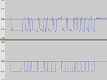
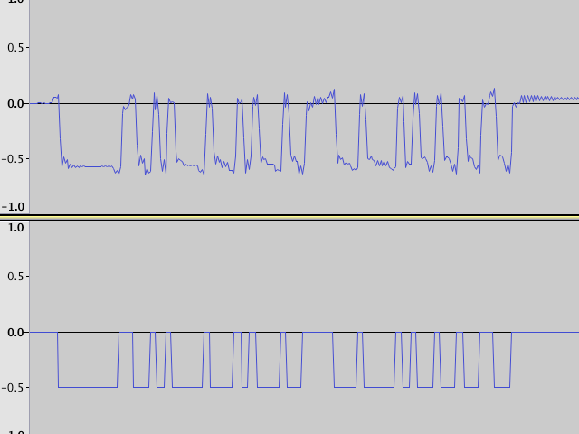
This screenshot show the signal recorded from the Arduino in the first channel, and the SuperCollider generated one in the second.
After all this, I could reverse the process, generate any serial data and send it back to the Arduino RX pin (pin0). A small amplifier circuit in between helped to get a more stable communication going.
This serial-to-audio technique was used to control the 24 LEDs (6 PWM channels) in our Reflect installation i.e. SuperCollider is running on an iPod Touch and sends out serial audio to an ATmega168 microcontroller.
Here is another example that can fade a single led by sending serial commands over audio. Includes schematics for an amplifier circuit plus SuperCollider and Pure Data example code.