For an upcoming performance, I've revisited the electronics for my redUniform piece. My old setup used a Nordic nRF24L01 wireless chip but now I changed to WiFi and the Adafruit CC3000 module.
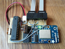
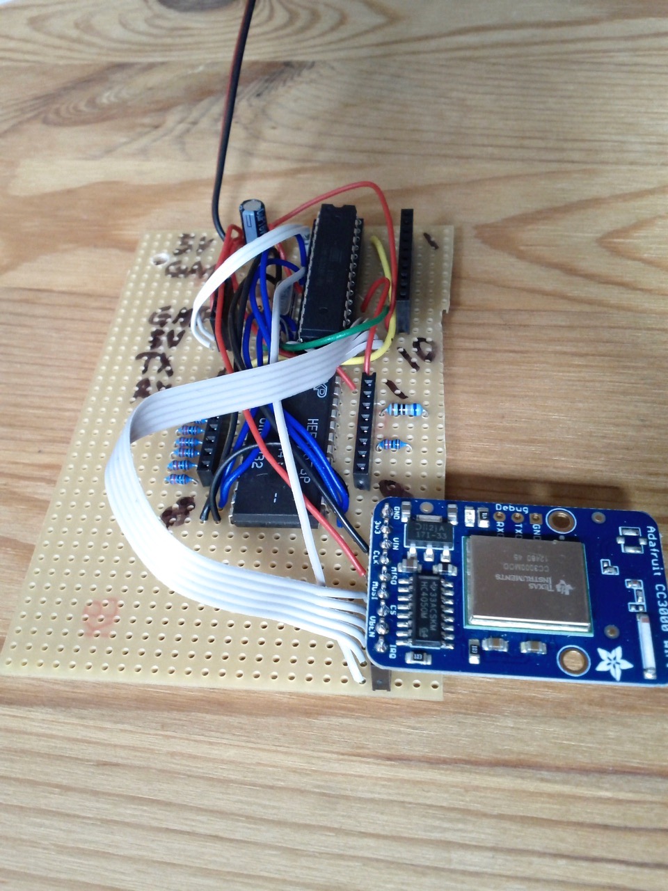
The circuit is minimal and simple. It's just the CC3000 WiFi module, an ATmega328, a 16Mhz crystal, an on/off switch, one 1000mAh Li-ion and last two 6p connectors for the sensors.
For a new piece I'm working on (redAlert), I wanted hundreds of red LEDs attached to special 'blobs' or lamps spread out on stage (designed by Jenny Michel). Each led should be able to be freely placed and controlled individually and they had to be fairly bright. And because of the custom led placement I couldn't have used led strips - strips have a fixed distance between the LEDs.
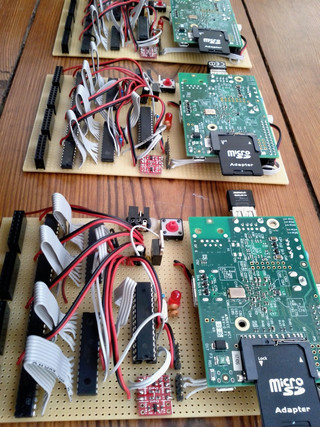
So I built three circuits that could drive 32 PWM channels each and thereby got 96 PWM channels in total. Each channel connects three LEDs in series (in a single package) and a resistor. That makes in total 288 LEDs.
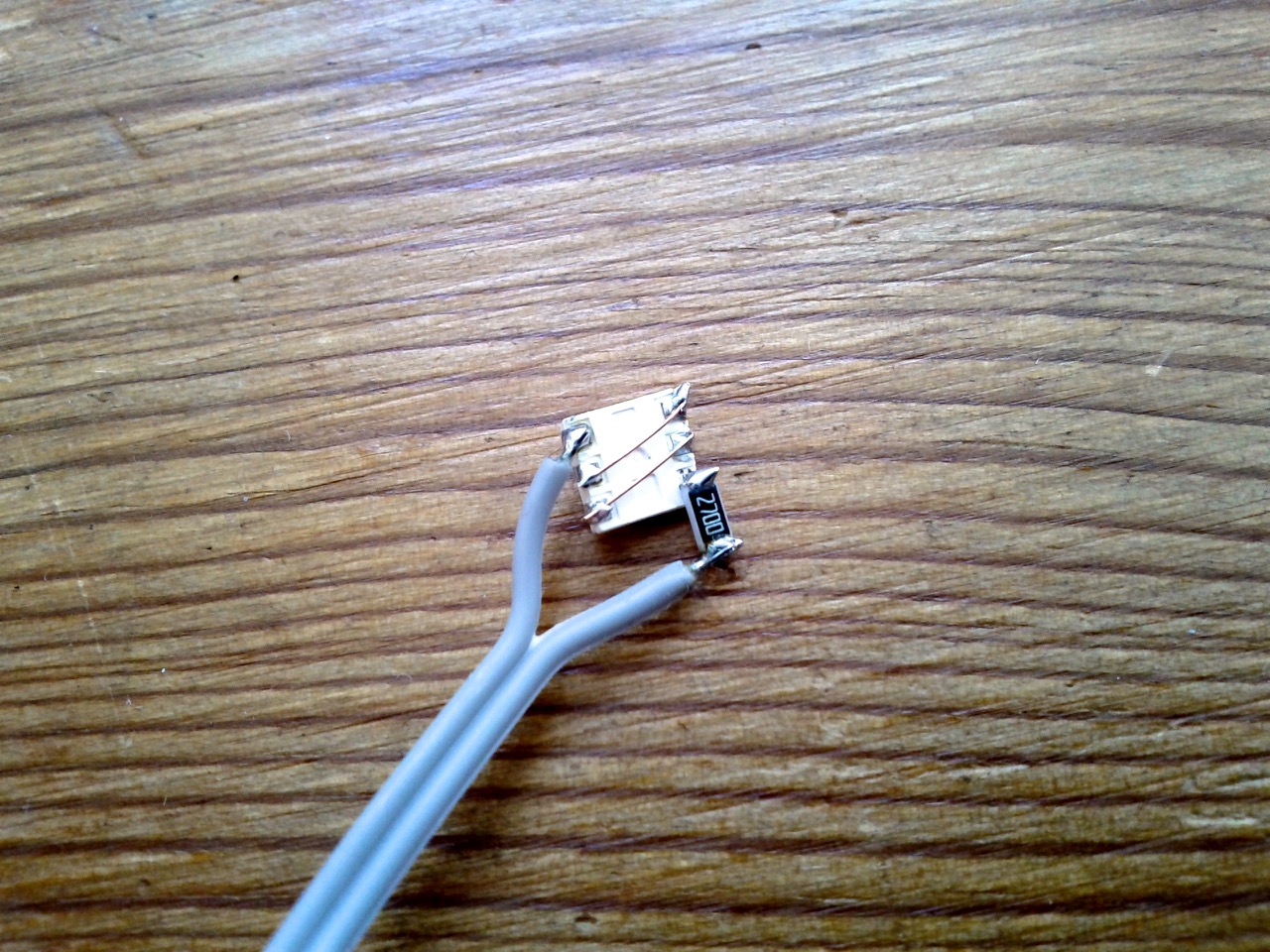
The led I selected was the LED 5252 uh rt/1700mcd. It has 120 degrees spread angle and comes in a 5x5mm 6pin SMD package that's possible to solder by hand. I bought it from Segor where it costs 0.42 Euro if you buy +100.
Here a picture of it from the backside. The 270 Ohm resistor is chosen to match 12V and the three LEDs are connected in series using thin copper wire.
The three boards are controlled wirelessly and I send OSC commands from SuperCollider to control all the LEDs. There's a class for SuperCollider attached below that helps with addressing and packaging of the network data. One can build and connect as many of these 32ch boards as one likes.
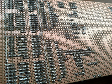
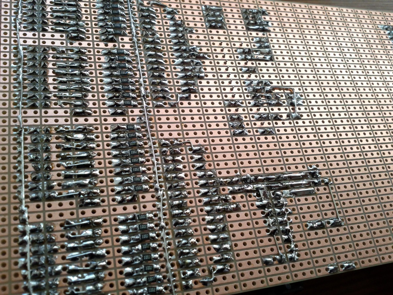
For actually generating the 12V PWM I used on each board two TLC5490 in combination with four ULN2803a. and I also added a barebone Arduino to get a stable SPI communication with the TLC5490.
Backside...
For receiving wireless OSC data I added a Raspberry Pi (model A) with an USB WLAN stick. On the RPi there's just a small Python program that receives OSC and sends out serial commands to the Arduino.
Last I have a TP-link TL-WR703N with Open WRT installed acting as a router. When the boards start, they try to connect to this router and gets an IP assigned dynamically. This IP I use in SuperCollider to differentiate between the three boards.
Installation instructions
* put 2013-09-25-wheezy-raspbian.img on an SD card with Pi Filler
* put the card in a Raspberry Pi MODEL B, connect ethernet and 5V
* find the IP with LanScan.app

(* ssh-keygen -R 192.168.1.51)
* ssh pi@192.168.1.51
* default password: raspberry
* sudo raspi-config
* select 'Expand Filesystem', change password, reboot and log in with SSH again

* sudo apt-get update
* sudo apt-get upgrade
* sudo pico /etc/inittab
* comment out the line 'T0:23:respawn:/sbin/getty -L ttyAMA0 115200 vt100' near the bottom and save
* sudo pico /boot/cmdline.txt
* remove 'console=ttyAMA0,115200 kgdboc=ttyAMA0,115200' and save
* sudo reboot

* sudo apt-get install python-serial
* git clone git://gitorious.org/pyosc/devel.git
* cd devel
* sudo ./setup.py install
* cd ~

//--set up WLAN on the RPi
* sudo nano /etc/network/interfaces
* edit to say...
  auto wlan0
  allow-hotplug wlan0
  iface wlan0 inet dhcp
    wpa-ssid SSID_NAME
    wpa-psk SSID_PASS
    wireless-power off
* sudo ifdown wlan0
* sudo ifup wlan0

//--copy file from laptop to RPi
* scp redAlertLight.py pi@192.168.1.51:/home/pi/

//--automatically start the Python program at startup
* sudo pico /etc/rc.local
* add the following before the exit line: (sleep 1; python /home/pi/redAlertLight.py) & # autostart

//now move the SD card over to model A, connect the circuit and try

//--useful if you log in via SSH and want to stop the Python program
* sudo pkill python
Here is the Python code...
#redFrik 2013

import serial
import socket
import OSC
import threading
import time
import os

addy= '0.0.0.0', 15000  #from SC
osc_server= OSC.OSCServer(addy)

port= serial.Serial('/dev/ttyAMA0', 115200)  #to ATmega168
port.open()

def osc_led(addr, tags, data, source):
  #print tags
  #print "incoming OSC data: %s" % data
  arr= bytearray()
  arr.append(254)
  for val in data:  #data has size 16 (24bit ints)
    hi_val= val>>12
    lo_val= val&4095
    #here can be optimized later to send fewer bytes (48 instead of 64)
    arr.append(hi_val>>8)
    arr.append(hi_val&255)
    arr.append(lo_val>>8)
    arr.append(lo_val&255)
  arr.append(255)
  port.write(arr)

osc_server.addMsgHandler("/led", osc_led)

def osc_stop(addr, tags, data, source):
  #print tags
  #print "shutting down"
  shutdown()

osc_server.addMsgHandler("/stop", osc_stop)

thread= threading.Thread(target= osc_server.serve_forever)
thread.start()

def all_led_off():
  osc_led(None, None, [0, 0, 0, 0, 0, 0, 0, 0, 0, 0, 0, 0, 0, 0, 0, 0], None)

def shutdown():
  close()
  os.system("sudo halt")
  exit()

def close():
  print "\nclosing"
  osc_server.close()
  all_led_off()
  port.close()
  #thread.join()

def main():
  try:
    while True:
      line= port.readline()
      if line.startswith("stop"):
        shutdown()
  except KeyboardInterrupt:
    close()

if __name__ == "__main__":
  main()
Attached are schematics, Arduino firmware, parts list...
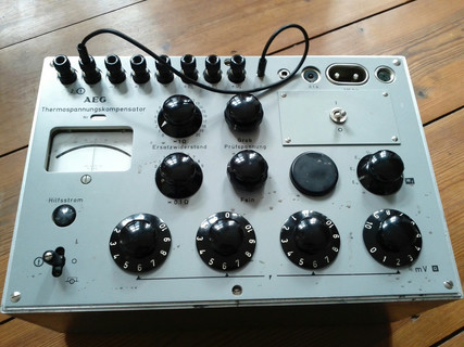
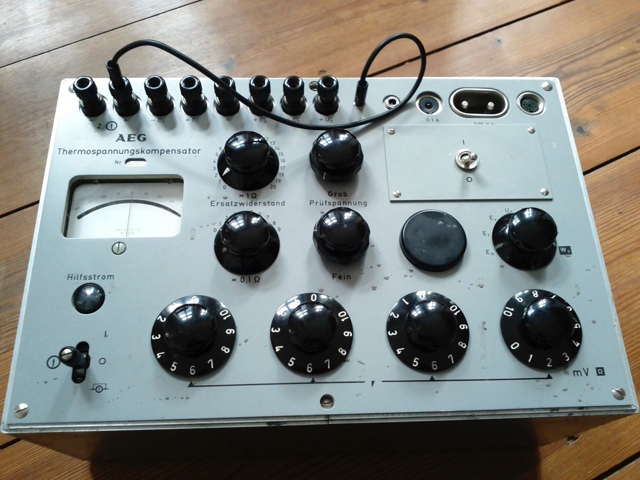
For my upcoming solo at the Sound of Stockholm festival, I decided to rebuild my main wireless controller. Previously it used a Nordic nRF24L01+ transceiver as radio module, but the range wasn't great and communication often broke down during live performances. I don't know much about these things, but I guess that when the audience bring in mobile phones the radio spectrum quickly fills up.
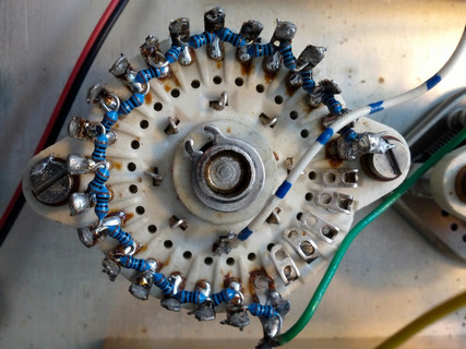
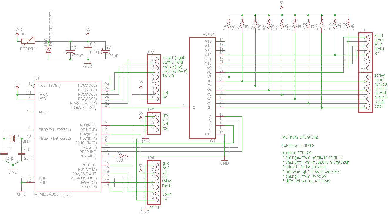
So I constructed a new circuit from scratch and while I was at it also reworked the resistor ladders and other cablings inside the box. Now it's using WiFi. The new radio module I installed in the controller box is Adafruit's CC3000 WiFi Breakout, and as receiver, I use a small tl-wr703n WiFi router running OpenWRT.
The wireless range is now excellent and everything is a lot more stable. I could also drastically reduce the amount of data being sent by fixing the resistor ladders.
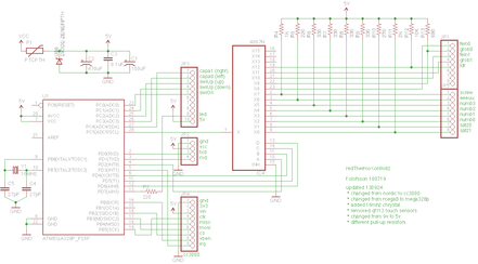
Circuit... (basically just one ATmega382p, a 16 channel ADC, voltage divider resistors and the WiFi module)
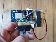
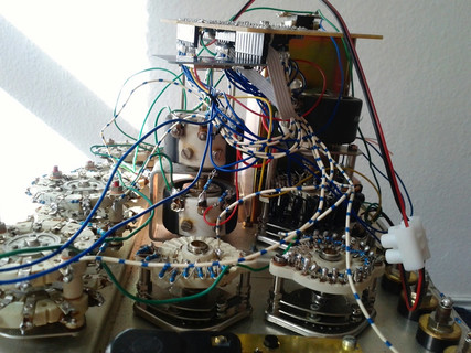
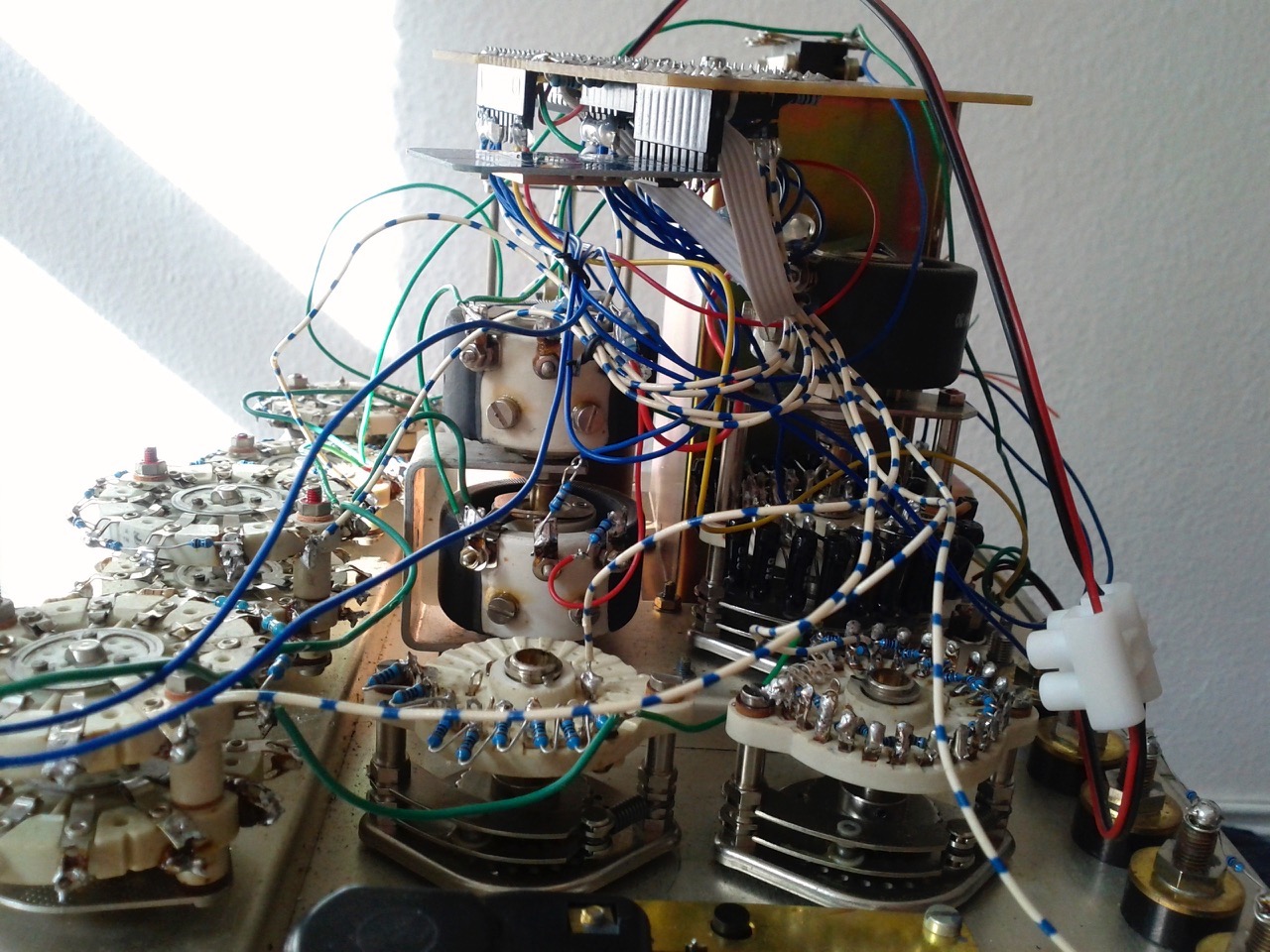
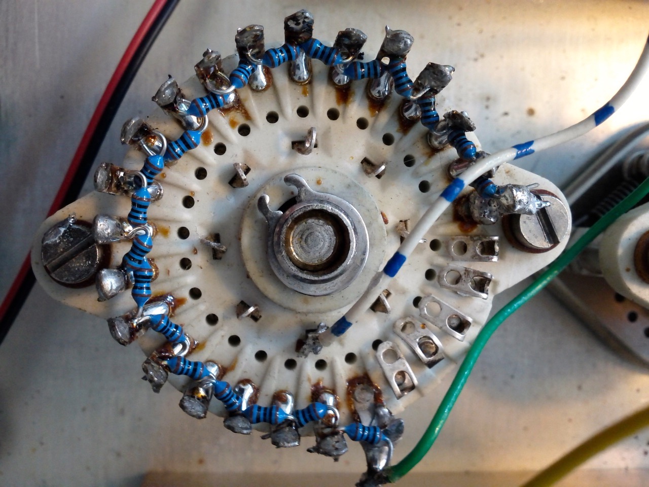
Inside...
Outside...
100 Ohm resistor ladder...
Below are parts list, schematics, firmware and a SuperCollider class.
redThermoKontroll (WiFi version) parts list:

1   4067 multiplexer
1   ATmega328p
1   16 MHz crystal
2   27p ceramic caps
1   socket 2x14 (28pin)
1   Adafruit CC3000 module
1   1x9 pin header
1   1x10 pin header
1   1x8 pin header
1   1x5 pin header

1   resettable fuse 1A
1   Zener diode 5.6V
1   0.1uF cap
1   100uF electrolytic cap
1   470uF electrolytic cap

10  220, 270, 330, 680, 1K, 2, 10K resistors
1   220 resistor for led

1   power jack
1   LDR
1   red led
//redThermoKontroll2
//redFrik 2013 GNU GPL v2
//updated 150920 - automatically send to IP x.x.x.99 (constructed from given DHCP IP)

//make sure to use Paul Stoffregen's branch of the Adafruit_CC3000 library
//and cc3000 firmware 1.24 (1.11.1)
//select board UNO and upload to a ATMEGA328P chip (using a usbtinyisp programmer)
//test in terminal with command: nc -ul 58100

#include <Adafruit_CC3000.h>
#include <ccspi.h>
#include <SPI.h>

#define WLAN_SSID       "xxx"
#define WLAN_PASS       "yyy"
#define WLAN_SECURITY   WLAN_SEC_WPA2

#define PORT            58100
#define DELAY           10
#define PINGRATE        2000

#define ADAFRUIT_CC3000_IRQ   3   //mega328 pin 5
#define ADAFRUIT_CC3000_VBEN  8   //mega328 pin 14
#define ADAFRUIT_CC3000_CS    10  //mega328 pin 16
Adafruit_CC3000 cc3000 = Adafruit_CC3000(ADAFRUIT_CC3000_CS, ADAFRUIT_CC3000_IRQ, ADAFRUIT_CC3000_VBEN, SPI_CLOCK_DIVIDER);
Adafruit_CC3000_Client client;

uint8_t buf[16];
byte last[] = {
  0, 0, 0, 0, 0, 0, 0, 0, 0, 0, 0, 0, 0, 0
};

byte cnt = 0;
unsigned long time;

void setup(void) {
  Serial.begin(115200);  //debug

  //--pins
  pinMode(7, OUTPUT);         //led
  pinMode(6, OUTPUT);         //4067 d (DDD6)
  pinMode(5, OUTPUT);         //4067 c (DDD5)
  pinMode(4, OUTPUT);         //4067 b (DDD4)
  pinMode(2, OUTPUT);         //4067 a (DDD2)
  pinMode(A5, INPUT);         //4067 x
  pinMode(A4, INPUT_PULLUP);  //capa1 (right)
  pinMode(A3, INPUT_PULLUP);  //capa0 (left)
  pinMode(A2, INPUT_PULLUP);  //swiUp (up)
  pinMode(A1, INPUT_PULLUP);  //swiUp (down)
  pinMode(A0, INPUT_PULLUP);  //swiOn

  //--wifi
  flash(1);
  Serial.println(F("Starting"));
  if (!cc3000.begin()) {
    Serial.println(F("Unable to initialise the CC3000! Check your wiring?"));
    while (1);
  }
  flash(2);
  Serial.println(F("\nDeleting old connection profiles"));
  if (!cc3000.deleteProfiles()) {
    Serial.println(F("Failed!"));
    while (1);
  }
  cc3000.connectToAP(WLAN_SSID, WLAN_PASS, WLAN_SECURITY);
  Serial.println(F("Connected!"));
  flash(3);
  Serial.println(F("Request DHCP"));
  while (!cc3000.checkDHCP()) {
    delay(100); // ToDo: Insert a DHCP timeout!
  }
  uint32_t ipAddress, netmask, gateway, dhcpserv, dnsserv;
  while (!cc3000.getIPAddress(&ipAddress, &netmask, &gateway, &dhcpserv, &dnsserv)) {
    Serial.println(F("Unable to retrieve the IP Address!"));
    delay(100);
  }
  Serial.print(F("\nCC3000 IP Addr: "));
  cc3000.printIPdotsRev(ipAddress);
  //the following sets receiver to x.x.x.99 and assume cc3000 will never get exactly that IP itself
  ipAddress = cc3000.IP2U32(ipAddress >> 24 & 255, ipAddress >> 16 & 255, ipAddress >> 8 & 255, 99);
  Serial.print(F("\nReceiver IP Addr: "));
  cc3000.printIPdotsRev(ipAddress);
  client = cc3000.connectUDP(ipAddress, PORT);

  //--OSC message [/tk2, index, value]
  buf[0] = 47;   // /
  buf[1] = 116;  // t
  buf[2] = 107;  // k
  buf[3] = 50;   // 2
  buf[4] = 0;
  buf[5] = 0;
  buf[6] = 0;
  buf[7] = 0;
  buf[8] = 44;   // ,
  buf[9] = 105;  // i
  buf[10] = 0;
  buf[11] = 0;
  buf[12] = 0;   //msb - index
  buf[13] = 0;   //
  buf[14] = 0;   //
  buf[15] = 0;   //lsb - value
}

void loop(void) {
  byte val;

  //--analogue inputs
  for (byte i = 0; i < 13; i++) {
    setChan(i);
    delay(1);                //not sure if needed
    val = analogRead(A5) >> 2; //from 10 to 8 bits
    if (val != last[i]) {
      sendOsc(i, val);
      last[i] = val;
    }
  }

  //--digital inputs
  val = PINC & 0b00011111;
  if (val != last[13]) {
    sendOsc(13, val);
    last[13] = val;
  }

  //--ping
  if (millis() - time > PINGRATE) {
    sendOsc(127, 0);      //ping
    time = millis();
  }
}

void sendOsc(byte index, byte val) {
  buf[12] = index;
  buf[15] = val;
  if (cnt++ % 2 == 0) {   //toggle red led
    PORTD &= ~_BV(DDD7);
  }
  else {
    PORTD |= _BV(DDD7);
  }
  client.write(buf, sizeof(buf));
  delay(DELAY);
}

void setChan(byte index) {
  switch (index) {
    case 0:
      PORTD &= ~_BV(DDD2);        //low
      PORTD &= ~_BV(DDD4);        //low
      PORTD &= ~_BV(DDD5);        //low
      PORTD &= ~_BV(DDD6);        //low
      break;
    case 1:
      PORTD |= _BV(DDD2);    //high
      PORTD &= ~_BV(DDD4);        //low
      PORTD &= ~_BV(DDD5);        //low
      PORTD &= ~_BV(DDD6);        //low
      break;
    case 2:
      PORTD &= ~_BV(DDD2);        //low
      PORTD |= _BV(DDD4);    //high
      PORTD &= ~_BV(DDD5);        //low
      PORTD &= ~_BV(DDD6);        //low
      break;
    case 3:
      PORTD |= _BV(DDD2);    //high
      PORTD |= _BV(DDD4);    //high
      PORTD &= ~_BV(DDD5);        //low
      PORTD &= ~_BV(DDD6);        //low
      break;
    case 4:
      PORTD &= ~_BV(DDD2);        //low
      PORTD &= ~_BV(DDD4);        //low
      PORTD |= _BV(DDD5);    //high
      PORTD &= ~_BV(DDD6);        //low
      break;
    case 5:
      PORTD |= _BV(DDD2);    //high
      PORTD &= ~_BV(DDD4);        //low
      PORTD |= _BV(DDD5);    //high
      PORTD &= ~_BV(DDD6);        //low
      break;
    case 6:
      PORTD &= ~_BV(DDD2);        //low
      PORTD |= _BV(DDD4);    //high
      PORTD |= _BV(DDD5);    //high
      PORTD &= ~_BV(DDD6);        //low
      break;
    case 7:
      PORTD |= _BV(DDD2);    //high
      PORTD |= _BV(DDD4);    //high
      PORTD |= _BV(DDD5);    //high
      PORTD &= ~_BV(DDD6);        //low
      break;
    case 8:
      PORTD &= ~_BV(DDD2);        //low
      PORTD &= ~_BV(DDD4);        //low
      PORTD &= ~_BV(DDD5);        //low
      PORTD |= _BV(DDD6);    //high
      break;
    case 9:
      PORTD |= _BV(DDD2);    //high
      PORTD &= ~_BV(DDD4);        //low
      PORTD &= ~_BV(DDD5);        //low
      PORTD |= _BV(DDD6);    //high
      break;
    case 10:
      PORTD &= ~_BV(DDD2);        //low
      PORTD |= _BV(DDD4);    //high
      PORTD &= ~_BV(DDD5);        //low
      PORTD |= _BV(DDD6);    //high
      break;
    case 11:
      PORTD |= _BV(DDD2);    //high
      PORTD |= _BV(DDD4);    //high
      PORTD &= ~_BV(DDD5);        //low
      PORTD |= _BV(DDD6);    //high
      break;
    case 12:
      PORTD &= ~_BV(DDD2);        //low
      PORTD &= ~_BV(DDD4);        //low
      PORTD |= _BV(DDD5);    //high
      PORTD |= _BV(DDD6);    //high
      break;
  }
}
void flash(int num) {
  for(byte i= 0; i<num; i++) {
    digitalWrite(7, HIGH);
    delay(100);
    digitalWrite(7, LOW);
    delay(100);
  }
}
Constrains - I love them. Inspired by Abe's twitter experiments, I've also played with creating small one line Processing programs that are 140 characters long.
Below is a video of number 0002, the twitter code tweets and screenshots. Note that many but not all are animations. Copy and paste the lines into Processing (2.0) to try them out.
NOTE: several stopped working under version Processing 3 and above. To make them run replace size(s,s); with size(900,900); i.e. width and height can no longer be variables.
p5tweet0002
0001
int i;noStroke();size(999,900);for(i=0;i<999;i++){fill(255,0,0,9);rect(i%99,i,i,i);}for(i=0;i<999;i++){fill(0,200,0,3);rect(i,i,i,i);}// #p5
0002
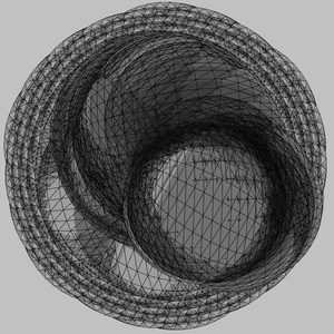
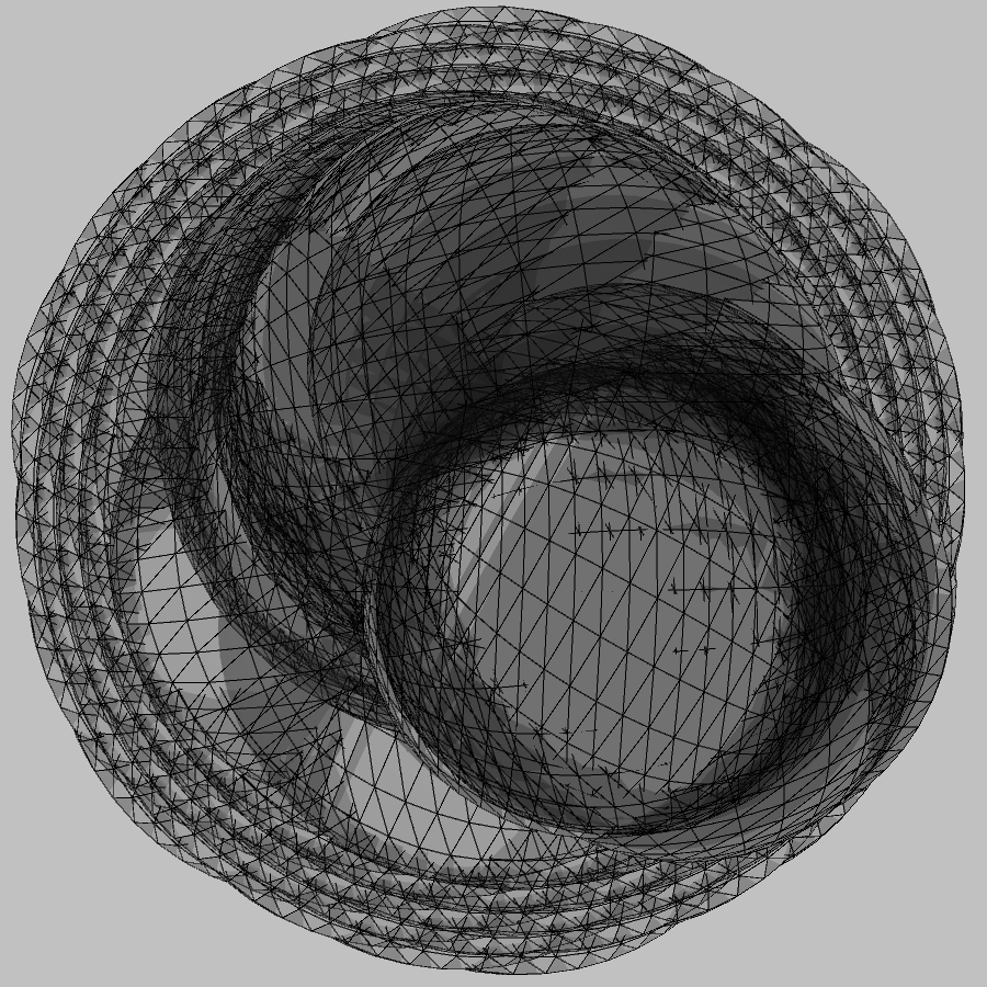
int j,i=0;void setup(){size(1200,900,P3D);frameRate(999);}void draw(){for(j=0;j<99;)rect(i++%(1199-j++),int(i/99)%(999-j),i%12,j%16);}// #p5
0003
int s=900,j,i=j=0;void setup(){size(s,s);fill(0,9);textSize(80);}void draw(){text(i+j,(sin(i++)/3+0.3)*s,(cos(j+++(i/4e3))/3+0.5)*s);}// #p5
0004
int s=900,j,i=j=0;void setup(){size(s,s);stroke(255,9);fill(9,3);}void draw(){quad(i++,j++,j,i,s-i,i-50,s-j,j);i=(i<<j%4)%1200;j=j%s;}// #p5
0005
int s=900,i=0;void setup(){size(s,s,P3D);stroke(255,0,0);fill(10,4);}void draw(){translate(i++%s,s/2);rotate(float(i)/s);sphere(i%s);}// #p5
0006
int s=900;float i=0;void setup(){size(s,s,P3D);stroke(99,9);fill(0,2);}void draw(){translate(i++%s,s/2);rotate(cos(i/50));box(i%s/3);}// #p5
With lots of study of the AudioBoot_V2_0 Java code by Chris at roboterclub-freiburg.de, I managed to write SuperCollider code for uploading sketches to an Arduino via the soundcard. No FTDI chip needed!
It's a very cheap solution for programming barebone Arduinos (well, ATmega168 microcontrollers really). You only need a few resistors, a capacitor and a mega168. The only difficult part is to initialize this microcontroller by burning the special bootloader on to it. This requires an AVR programmer of some sort (STK500, USBtinyISP etc).
After that one can compile HEX files in the Arduino IDE and upload them using SuperCollider and a standard audio cable.
1. Burn the bootloader on to a mega168
The trick behind all this is the special sound enabled bootloader that I found here... www.hobby-roboter.de/forum/viewtopic.php?f=4&t=127. I downloaded the AudioBoot_V2_0.zip file and used my STK500 AVR programmer together with the great AVR Crosspack. The terminal command I used for burning the bootloader was the following...
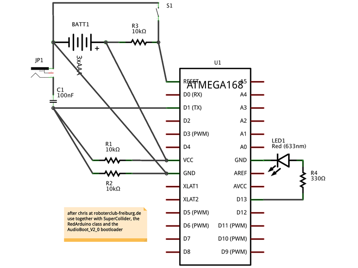
audioino circuit schematics (made by me using Fritzing - it's quite confusing)
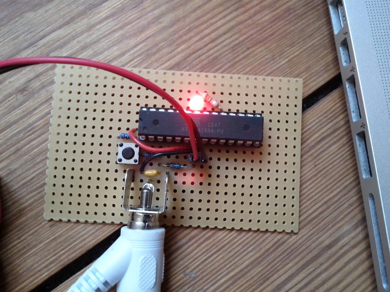
audioino protoboard circuit photo
I run it off 4.5V (3 batteries) but it could also be powered from the USB port.
3. Prepare the Arduino IDE
To compile HEX files for this barebone Arduino, I needed to set up a custom board in the Arduino IDE. One way to do this is to create a new text file called boards.txt and put it inside a new folder in the Arduino/hardware folder. on macOS that could be something like ~/Documents/Arduino/hardware/BareBones/boards.txt.
The boards.txt should contain the following...
minimal168.name=ATmega168 bare bone (internal 8 MHz clock)
minimal168.upload.speed=115200
minimal168.bootloader.low_fuses=0xE2
minimal168.bootloader.high_fuses=0xDD
minimal168.bootloader.extended_fuses=0×00
minimal168.upload.maximum_size=16384
minimal168.build.mcu=atmega168
minimal168.build.f_cpu=8000000L
minimal168.build.core=arduino:arduino
minimal168.build.variant=arduino:standard
Then restart the Arduino IDE and under the boards menu, there should be a new option with mega168 and 8 MHz internal clock. I make sure this board is selected every time before compiling HEX files for sound uploading.
Another thing that needs to be done is to enable 'verbose compile' in the Arduino IDE preferences. That will print out the file path of the HEX file each time you compile a sketch.
4. Install the RedArduino class
I wrote a couple of classes for SuperCollider to help with the encoding and signal generation of HEX files. They're found in my redSys quark (under redTools) and are most easily installed from within SuperCollider itself with these commands...
Quarks.install("redSys"); //install. recompile after this
There are two helper classes and one main class. The RedIntelHex class parses HEX files and RedDifferentialManchesterCodeNegative helps to encode the signal as differential manchester code. The main class RedArduino figures out the paging of data and generates a bitstream that is played back using demand rate UGens.
Uploading
I upload sketches by compiling them in Arduino IDE (click verify - not upload) and copy&paste the file path of the resulting HEX file into SuperCollider and the RedArduino's read method. I connect the left sound output channel to the barebone Arduino, put my mac laptop volume to ~80%. Last I press the reset button on the circuit and quickly (within seconds) call the upload method in SuperCollider. The led should blink slowly directly after a reset, and fast when receiving data.
Here's a video demonstrating how to do it. I'm just uploading the simple Blink example. Near the end, you will also hear how that sounds.
audioino - uploading an Arduino blink sketch via sound
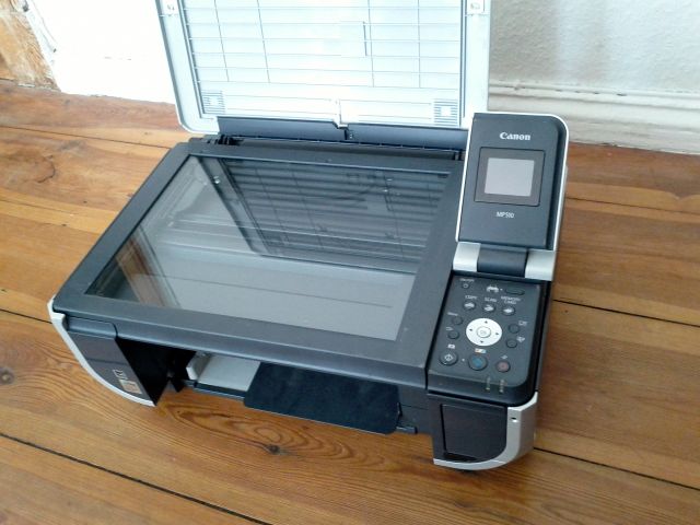
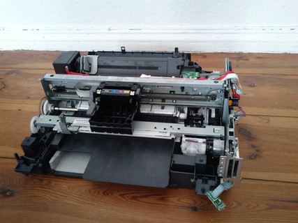
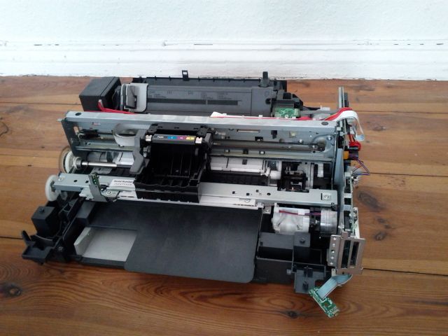
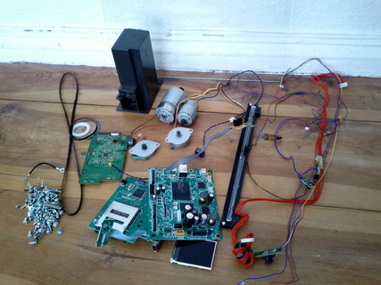
Some weeks ago I found a Canon Pixma MP510 on the street. A "Photo All-in-One with economical single inks that prints, copies or scans in colour". Someone had thrown it away regarding it as a piece of junk. I saw a pile of gold.


