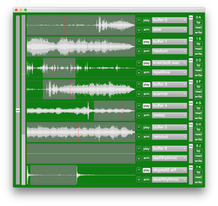
Player behaviours include in which direction and how fast to progress in the captured sound buffer, when to play for how long, with which envelope and how loud, how much transposition, play in which audio channel etc.
Some of these players are using granular synthesis techniques while others are scratching and jumping around in the sound buffer in more or less unpredictable ways. Hopefully, the names listed here above will give a hint of what players do to the sound.
All players are pieces of code. For example this the code for the scanner player...
SynthDef(\scanner, {|buf, amp= 1, start= 0, end= 1|
  var dur= BufDur.kr(buf);
  var pha= LFNoise2.kr(In.kr(100)+0.1)+1/2;
  var pos= pha*(end-start)+start;
  var add= LFNoise2.kr(1);
  var fre= In.kr(101).linexp(0, 1, 1.1, 18)+add*SinOsc.kr(0.1).max(0.5);
  var snd= TGrains.ar(
    2,
    Impulse.ar(fre),
    buf,
    1+LFNoise2.kr(1, 0.05),
    pos*dur,
    0.75,
    LFNoise2.kr(0.06, 0.5),
    amp.lag(0.5)
  );
  SendReply.kr(Impulse.kr(\updateRate.kr+1), '/pos', pos);
  Out.ar(\syncBus.ir(40)+\index.ir, K2A.ar(pha));
  snd= CompanderD.ar(snd, \compressorThresh.kr, 0.5, 0.5, 0.005, 0.01, EnvGate());
  Out.ar(\out.kr, snd);
}).add;
and most players will look very similar to this. But there are also a few special ones like sync which just matches the playback position of the player in the track above.
In the main window one can also set track volume, bypass any global effects and read/write sound files.
The computer keyboard may be used for shortcuts quickly arming, playing and selecting what each track should play.
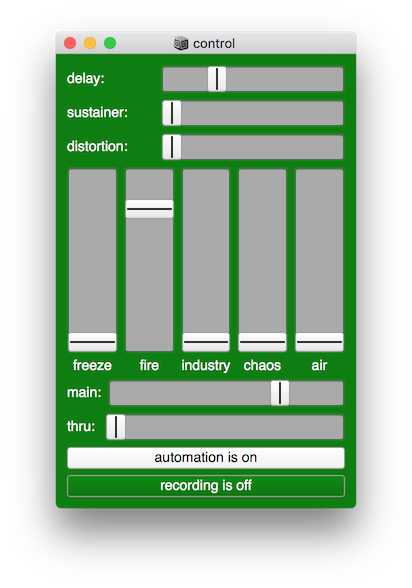
Global control
There is also an additional control GUI with global volume, effects, automation and record...
The three sliders delay, sustainer, distortion are just simple wet/dry control for global effects (that can be bypassed for each track using the bp button), while the other sliders freeze, fire, industry, chaos, air are more complex and control a bunch of effects and behaviours. For example, freeze will take the sound from all players and smear it out by removing transients and pitch shifting copies of the sound up/down in octaves.
When the automation button is clicked, the program itself can start and stop tracks, change effects and vary a lot of other parameters in the code. The idea here is that the software should be able to run independently and generate interesting variations over long periods of time. Also, it should never go completely silent nor go wild and overload everything.
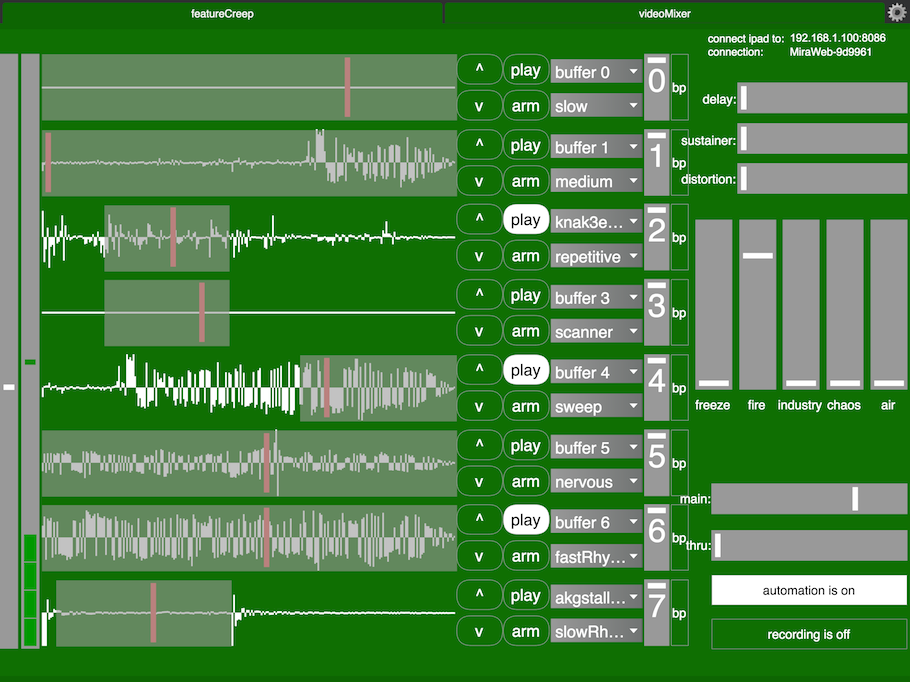
Remote iPad interface
All the above can be viewed and controlled remotely from a tablet or a phone using a web browser. We programmed a look-alike GUI patch with MaxMSPJitter and the mira externals. This patch talks to the SuperCollider interface over Open Sound Control.
featureCreep screenshot from iPad interface
The interface here is even more ugly - especially the waveform display because the sound data had to be downsampled and kept at a low resolution to reduce wifi network traffic. Also, it was hard to fit everything on a single screen as all widgets had to be quite large and not too close to each other to be usable on an iPad.
Our software also includes a video mixer for camera and movie playback (not shown here).
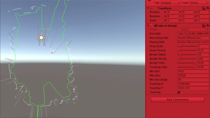
A much-improved version of my old MaxMSPJitter application anneVideotracking
screenshot
With this version, you can use 12 zones on a web camera video input to trigger MIDI, sound files, audio input (mics) and OSC messages (send to SuperCollider for example).
The zones include filters and different types of thresholds and calibration. The data can be on/off triggers and or continuous values.
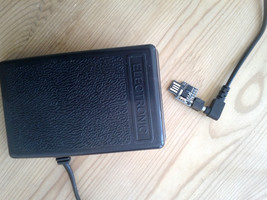
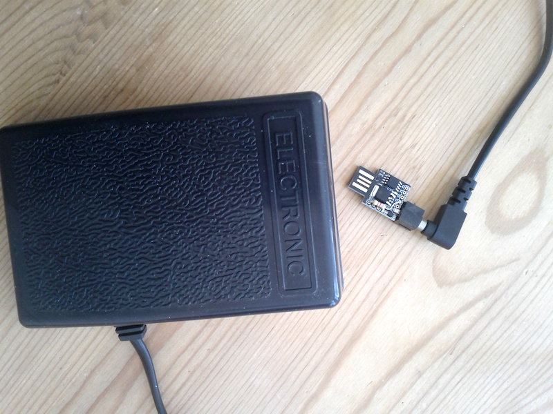
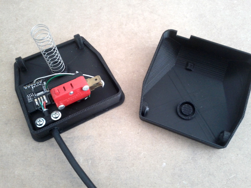
Here's how I built a USB foot pedal that sends out MIDI CC messages as well as note on/off messages when crossing some threshold.
To get a rugged pedal I bought a sewing machine foot pedal/speed control. For converting to MIDI and connecting to a computer I used a Digispark module. The two other parts needed are a 3.5mm socket and a 4K7 resistor.
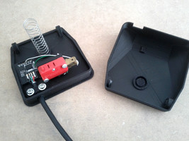
pedal - photo
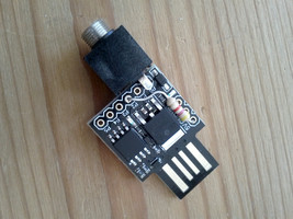
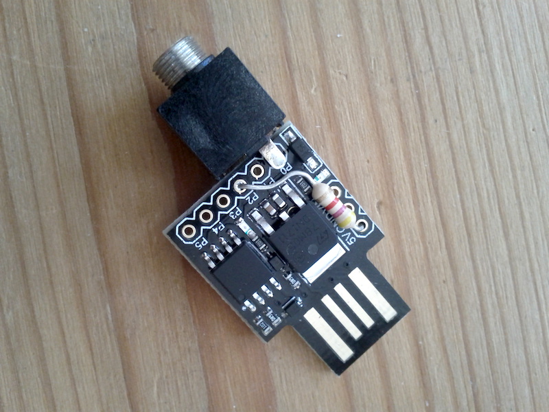
pedal - closeup of circuit
The code for the Digispark is really simple and I programmed it from the Arduino IDE. THRESH_HI and THRESH_LO together with the state variable implement hysteresis, and lastVal is used to filter out any repeating values.
//with Digispark (Default - 16.5MHz)
//connect 4.7K resistor between tip and 5V, tip to P2 and sleeve to GND

//usb yellow or red     5V
//usb white             data-
//usb green             data+
//usb grey or black     GND

#define USB_CFG_DEVICE_NAME     'm','i','d','i','P','e','d','a','l'
#define USB_CFG_DEVICE_NAME_LEN 9
#include <DigiMIDI.h>

#define PINLED 1      //onboard led
#define PINSENSOR A1  //foot controller sensor (P2)
#define PINGND 0      //ground
#define CTRL 7        //midi controller (cc)
#define NOTE 99       //midi note
#define VELO 64       //midi velocity
#define CHAN 9        //midi channel
#define THRESH_HI 100 //0-127
#define THRESH_LO 50  //0-127

DigiMIDIDevice midi;
int lastVal = 0;
int state = 0;

void setup() {
  pinMode(PINLED, OUTPUT);
  pinMode(PINGND, OUTPUT);
  digitalWrite(PINGND, LOW);
  midi.sendNoteOff(NOTE, VELO, CHAN);
}

void loop() {
  midi.update();
  int val = analogRead(PINSENSOR);
  val = constrain(val, 9, 900);
  val = map(val, 9, 900, 127, 0);
  if (val != lastVal) {
    midi.sendControlChange(CTRL, val, CHAN);
    if (state == 0 && val > THRESH_HI) {
      midi.sendNoteOn(NOTE, VELO, CHAN);
      digitalWrite(PINLED, HIGH);
      state = 1;
    } else {
      if (state == 1 && val < THRESH_LO) {
        midi.sendNoteOff(NOTE, VELO, CHAN);
        digitalWrite(PINLED, LOW);
        state = 0;
      }
    }
    lastVal = val;
  }
  midi.delay(100);
}
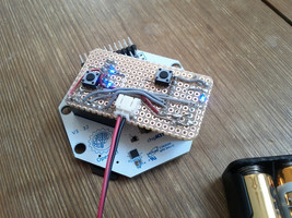
For another project, I also made a 3D printed variant. This one is not so rugged and only acts as an on/off switch. It's based on Adafruit's USB_Foot_Switch_Controller but modified to fit a Digispark.
3D printed pedal
Arduino code for this discrete pedal (only note on/off)...
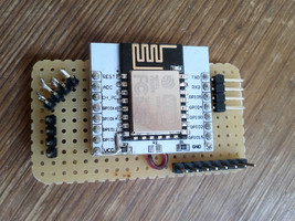
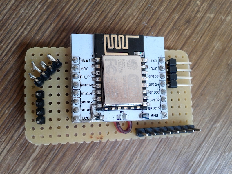
On the white adapter board, I first removed the 0K resistor link in the middle (R2). Then I cut the two tracks that run from VCC to the left-hand side 10K resistor (R3). Next, I soldered on an NCP1117 on the backside (not visible in the photo) and finally added two 100nF caps.
Last I mounted the ESP+adapter on a Vero board, added male pin headers and the other components and wires.
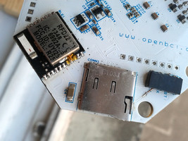
This documents a repair of a Cyton board. The board would turn on and kind of work but one couldn't upload new firmware to it.
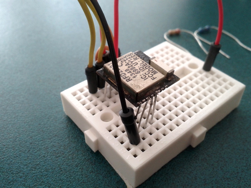
I localised the issue to the RFD22301 (aka RFDuino) module. To desolder it from the board I used some rose's metal - a material with low melting temperature (94°c) - and then put on new temporary pins to a few pads and put it on a breadboard.
repairing a RFDuino
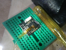
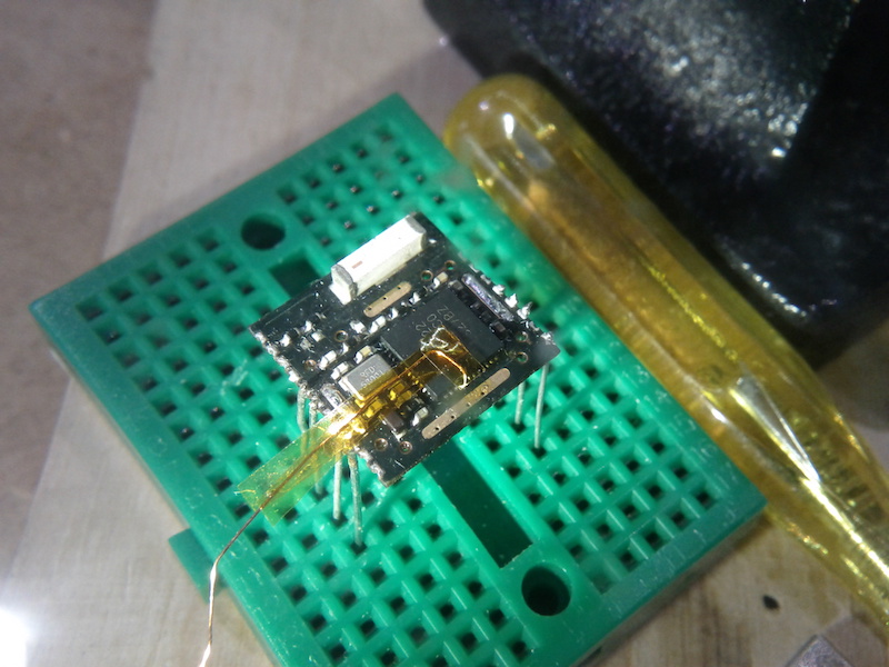
The module sort of worked but it still wouldn't be programmed. After lifting the metal shield and checking all the connections, I found a broken trace from the chip out to the rf_rxd pad (gpio0/aref) on the module. Tracing the fault a bit further it turned out to be a broken via. I tried to refill the via with solder but it was just too small to repair. So I ended up adding a thin copper wire directly from the pin to the pad and wrapped it in some Kapton tape for isolation.
RFDuino without metal can
I had to cut out a slot in the metal shield so that my wire could get out without getting squeezed and shorting to ground. It doesn't look pretty, but the module now worked and I could finally upload new firmware. And after soldering the shield back and putting back the module, the Cyton board worked again.
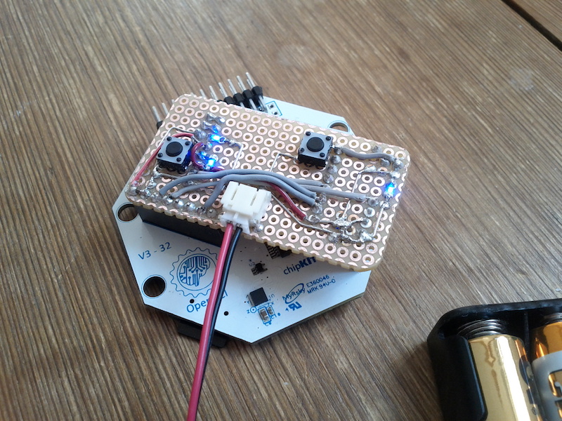
Working RFDuino back on Cyton board
I also repaired a broken trace on one of the serial lines. It's visible on the right-hand side in the photo.
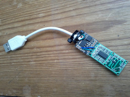
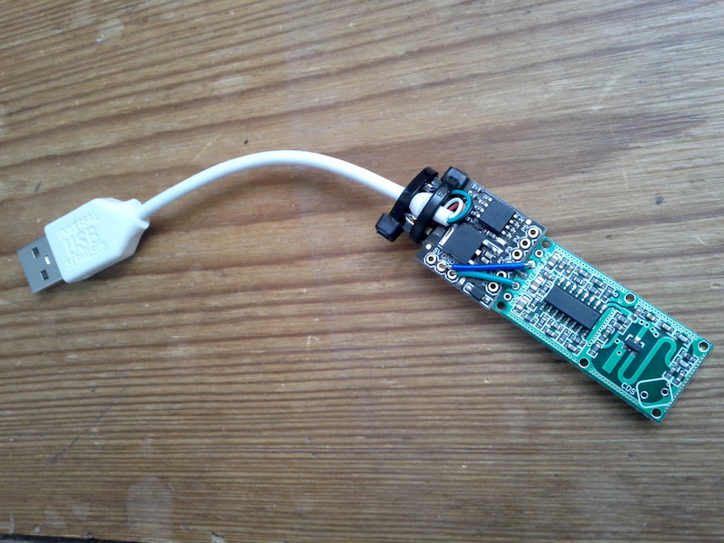
Last year I built this very simple motion detection device. It will trigger a noteOn MIDI message when someone enters a room, and a noteOff message when there's no activity. It's using a RCWL-0516 radar sensor and a Digispark clone (basically a ATtiny85).